Some issues back I wrote a riveting three-part series about AN nuts, bolts and washers. The film rights were picked up by EAA and the series was turned into a webinar called The Nuts and Bolts of Nuts and Bolts. It skipped the theaters, never came out on DVD. However, on the heels of that brush with success my reader asked me to address rod end bearings. Mom, this one’s for you.
Rod end bearings are found terminating one or both ends of pushrods and, sometimes, control cables. Rod end bearings provide a self-aligning, friction-free interface between the moving parts of a control system as well as the means to adjust the functional length of a pushrod or control cable. That adjustability plays a key role in a rod end’s utility, as I shall describe with the following carefully chosen words about pushrods, but is also a potential point of failure. (Insert suspenseful music here.)
Carefully Chosen Words About Pushrods
Pushrods (and control cables) connect the moving parts of flight and engine control systems. They often bridge long distances and slash through airframes at unusual—sometimes varying—angles. Rod ends at one or both ends of a pushrod provide a low-friction interface between the moving parts and accommodate subtle changes in the geometry of the connection. They also reconcile the inevitable manufacturing and assembly variations that should be expected in this less-than-perfect world—their threaded interface affords adjustment to the functional length of an otherwise fixed-length pushrod. Without that adjustability it would be impossible for kit companies to manufacture pushrods that would serve each builder’s needs. We builders would be left to make or modify each pushrod to account for myriad variations we can’t help but build into our artisan airframes.
If weight didn’t matter, a fully threaded pushrod, trimmed to the correct length by each builder, would be the ideal form for each pushrod. But weight does matter, so most pushrods—those of any length, anyway—are made from steel or aluminum tubing. A well-designed tube-type pushrod will maximize the length of the tube and minimize the length of terminating threads. But here’s an important caveat: To provide the maximum range of adjustment for rod ends, thereby maximizing the range of the pushrod’s functional length, a pushrod’s threads must be long enough to accommodate a rod end’s full range of safe engagement. Threaded lengths shorter than that hobble the utility of a rod end. Threaded lengths longer than necessary can impact the pushrod’s strength.
Can I Get a Witness?
There are three things that require a builder’s attention when fitting rod end bearings: ensuring adequate thread engagement, capturing the pressed-in bearing in the event of a rod end failure and preventing the rod end from migrating on the pushrod. Here is how each is addressed.
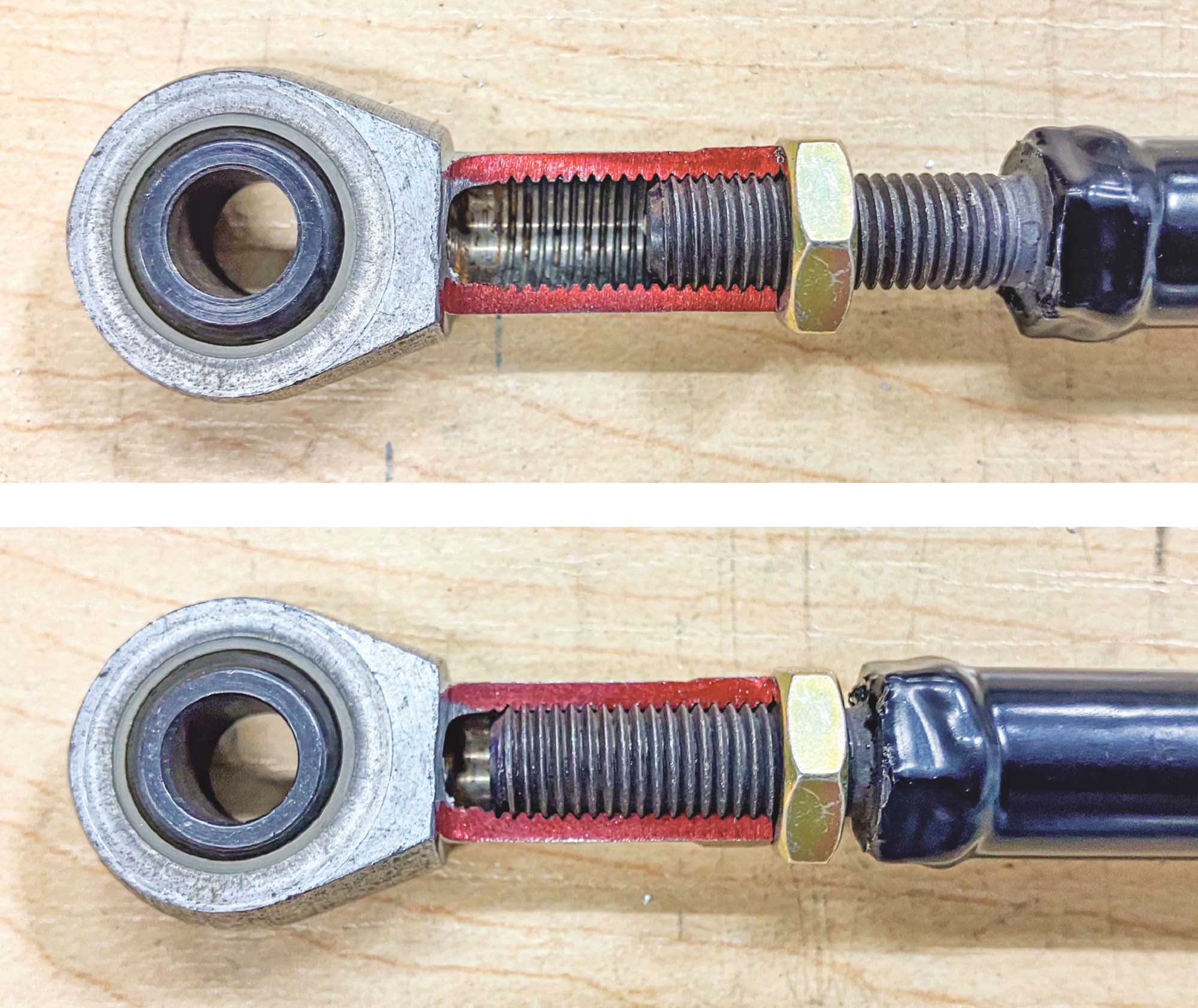
Witness Hole. A witness hole provides a means for visually or physically confirming the rod end has minimally engaged the push rod. What is minimum thread engagement? While a definitive specification from an authoritative source is elusive, it is widely accepted that the witness hole must be located 1 to 1.5 times the diameter of its thread size from the end of the rod end. For example, a 1/4-28 rod end must have a witness hole no less than ¼ inch from the end of the rod end. Many pushrods are manufactured with a witness hole. When one is absent, you must drill your own. I prefer a 1/16-inch witness hole, but I’ve seen them as large as 3/32 inch.
Male rod ends lack the convenience of a witness hole but still require minimum thread engagement. If a witness hole can’t be drilled in the corresponding pushrod, marking the male threads in some manner, such as “painting” them with a marker or machinist’s dye, works well.
Proper rod end engagement is achieved when the witness hole is completely blocked. When thread engagement can’t be visually inspected, use a piece of 0.020-inch safety wire to probe the hole. If the wire passes through, minimum thread engagement has not been achieved. Never accept less than minimum thread engagement.
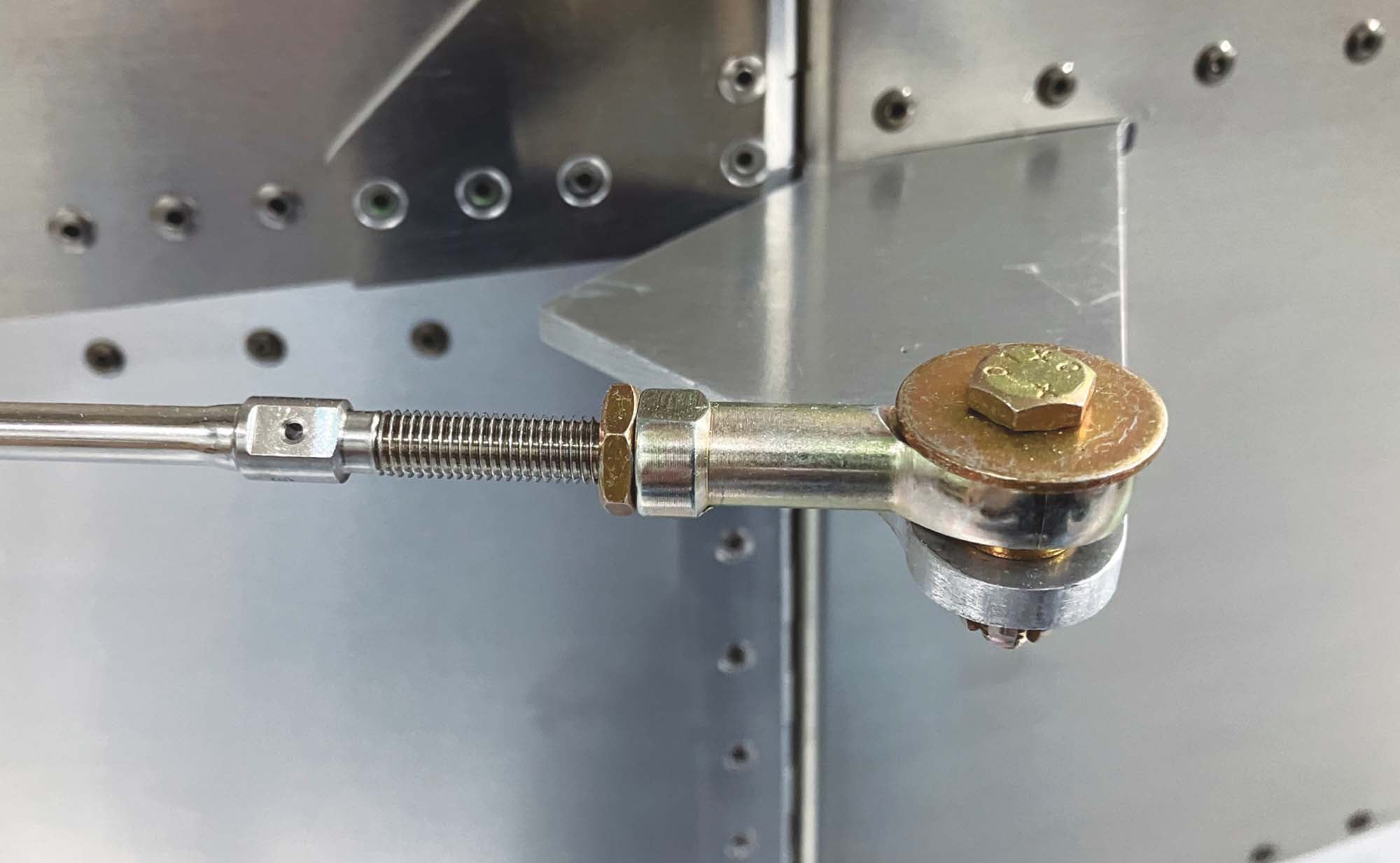
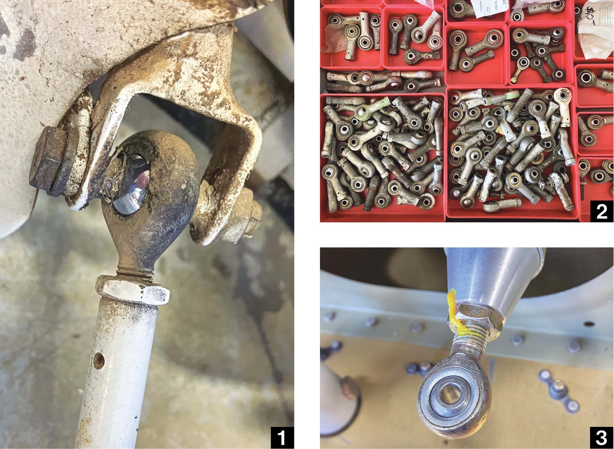
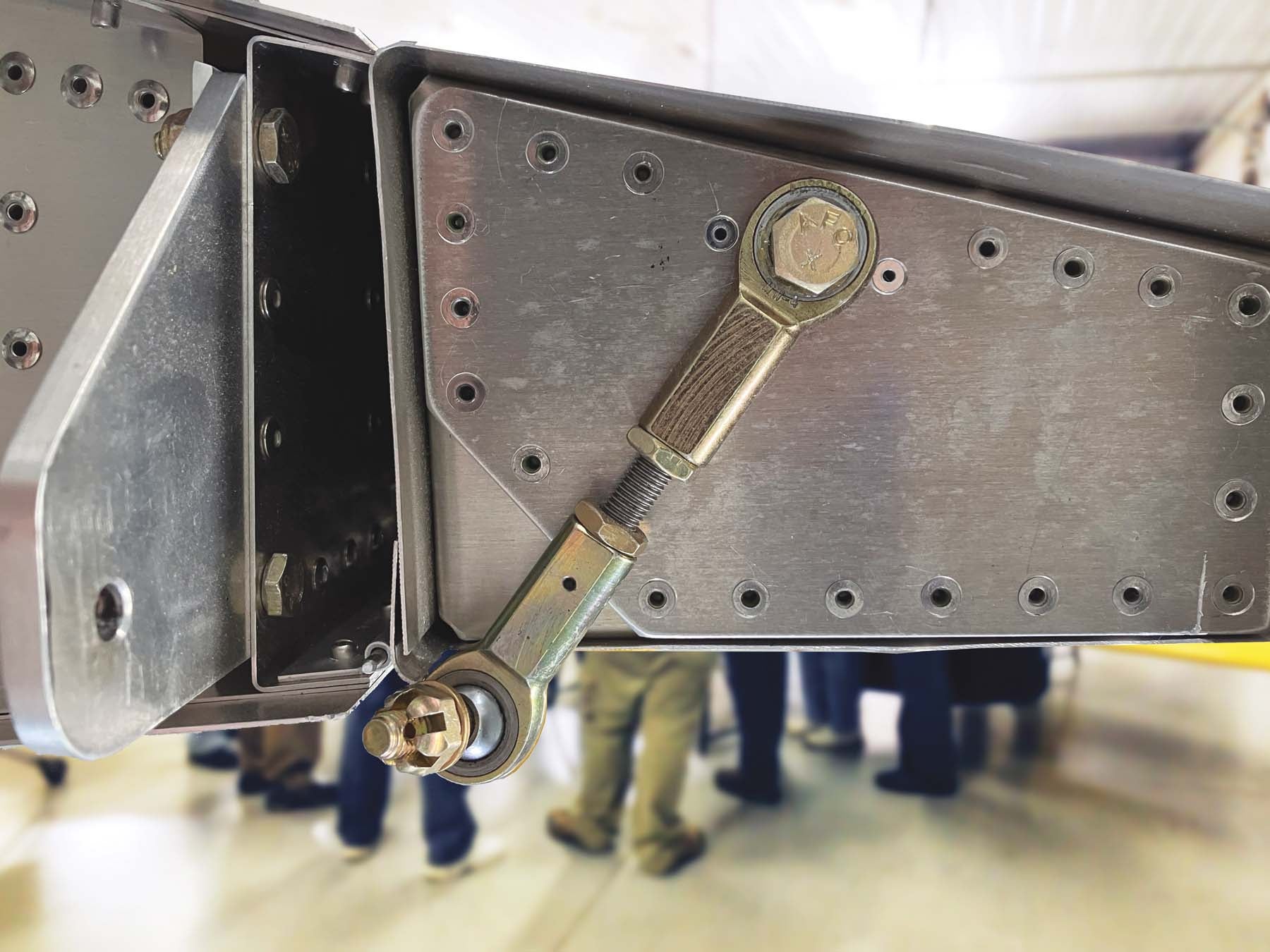
Capture Washer. Rod ends are typically a cast, forged or machined body with the bearing pressed in. That which can be pressed in can fall out if the rod end body cracks. If that happens the control linkage’s integrity is lost and dire consequences await. To prevent a full loss of rod end engagement, a large washer—typically an AN970 large area washer—is placed against any side of the rod end bearing that is not captured by other structure. The large washer keeps the bearing and rod end body in place in case they get separated. While the washer can’t prevent a failure, it can mitigate the consequences of a failure.
Check Nut. Rod ends are always paired with an AN316 check nut, sometimes called a lock nut or jam nut. The check nut prevents rod ends from rotating out of position. When installing female rod ends, the check nut is tightened against the rod end after the rod end has been adjusted. When installing male rod ends, the check nut is tightened against the pushrod after the rod end has been adjusted. A line of witness paint across the rod end and the jam nut, or jam nut and pushrod, adds a finishing touch.
Installing and Adjusting Rod Ends
Installing a rod end begins by making sure it has achieved minimum thread engagement. After that, deliberate adjustments can be made by turning the rod end farther onto the pushrod until the correct functional length has been achieved. If a pushrod has a rod end at each end, turn each rod end incrementally so they have equal thread engagement. After you’ve made the necessary adjustments, check once more that you have (at least) minimum thread engagement, lock the rod end in place with the check nut and paint both with witness paint.
If you run out of adjustment, do not accept that having less-than-minimal thread engagement is OK. It’s not. Something’s up and you need to find out what. Begin by checking that all the related parts are made and installed correctly. If you are dealing with kit parts, contact the kit manufacturer and lean on them for guidance in identifying and correcting the problem. It may be an incorrectly built or installed bellcrank or drive horn, an incorrect path between the two connecting points, an incorrectly manufactured part or a misunderstanding of what the plans are depicting. The problem needs to be identified and corrected. In my time supporting builders I encountered too many (and frankly, one is too many) builders who shrugged their shoulders, accepted what was before them and moved on without investigating why their assembly didn’t jibe with the factory documentation. That can have consequences that don’t become obvious until later, when the corrective action is much more involved.
As with most areas of homebuilding, one can dig as deep into a topic as one wishes or follow the accepted practices with little thought. I’m one who likes to know the “why?” of an accepted practice, as that gives me greater confidence, and flexibility, when executing a task. Installing rod ends is straightforward, but failing to recognize the potential points of failure can be catastrophic.


Great info. I also recommend a drop of #2 lok-tite in the threads of the rod to prevent the jam nut from backing off over time between conditional inspections
I would also add a fourth item. The rod ends should be aligned with each other in the same plain at the end of the tube so you get maximum rotation of the balls. You don’t want limited rotation of the balls.
Very helpful article. There is a nice beveled rod end retaining washer available from auto racing sources that allows a little extra bearing movement when you need it. Here is an example: https://www.pegasusautoracing.com/productselection.asp?Product=3068