Rod ends are commonly used in Experimental aircraft for hinges, the most common example being in the empennage of RV-series aircraft. From a strict structural engineering perspective, this is an “off-label” use, since the rods see bending loads perpendicular to the thread axis (nominal loads are tension/compression along the axis, and that is how they are rated). However, in our applications the loads are typically small enough to be safely handled by the rod end (though for history buffs I’ll point out that the 1991 crash of the race plane Tsunami was in part attributed to a failure of a rod end loaded in bending). For example, manufacturer Aurora limits the bending loads to just 10% of the nominal load stated in the catalog.
One of the advantages of using rod ends for hinges is that it makes aligning the rotational axis easier since you can adjust the length (x-axis) of individual rod ends in order to achieve collinearity for the whole control surface. (It’s up to you get the z-axis correct!)
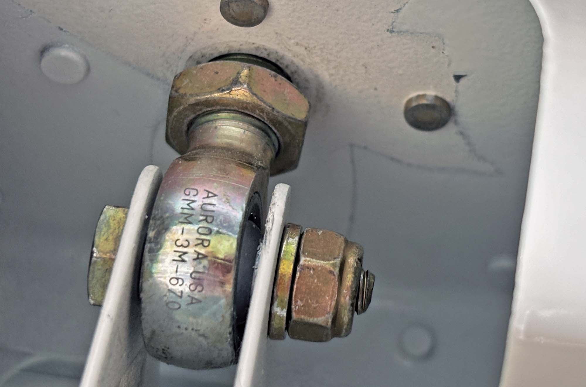
Since rod ends typically screw into a horizontal or vertical spar, the back side of which is often inaccessible, it is customary to use nut plates to secure the rod end. As Vic Syracuse has pointed out numerous times in his own articles, it is essential that a jam nut be incorporated in the rod end assembly as this not only helps prevent the rod end from loosening, but more importantly ensures that the rod end is primarily stressed in bending only from the point of the jam nut forward (minimizing stress on the rod end) and doesn’t transfer those bending loads to the nut plate.
Installation Tool
Screwing the rod end into the nut plate can be challenging. The trick is to grasp the body of the rod end without putting loads on the ball/race as the rod end is screwed in. There are several good DIY ideas on Doug Reeves’ VansAirForce.net (example). For my RV-4, I fabricated a tool from ABS and it worked fine. I liked that the tool won’t damage or mar the rod end. Avery also makes a tool similar to the one I describe that is available from Aircraft Tool Supply Company.
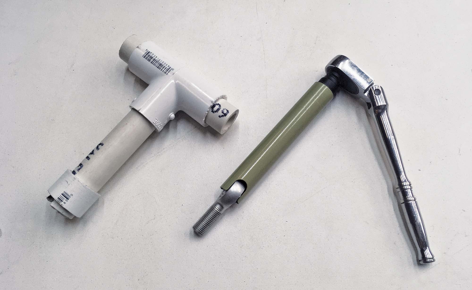
My SR-1 race plane uses rod end hinges for the empennage. Unfortunately, my ABS tool was too bulky to fit in the drag spar cove. I therefore constructed the low-profile tool shown at the beginning of this article. Material is simply a 4-inch length of ½-inch electrical metallic tubing (EMT) from the hardware store. I inserted a piece of 5/8-inch wooden dowel in the tubing and clamped it into the vise of my Bridgeport and milled a slot in the end with a 3/8-inch end mill. At the other end I drilled a 3/16-inch hole followed by a #12 reamer. A piano-wire hinge fitting pin (described below) is inserted into the hole and allows you to torque the rod end in.
Since the tool itself is a smaller diameter than the rod end, the cutout required for access is set by the diameter of the rod end body, not the tool. For folks who don’t care about a low-profile tool, slightly thicker wall aluminum tubing would be easier to machine. And since aluminum is softer than the steel rod end body, you’ll be less likely to mar the rod end as you torque it in.
The fancy version of this tool incorporates a 1/4-inch socket instead of the cross pin. I simply used a 10mm impact socket and epoxied it into the end of the tool. Works great!
Alignment Tools
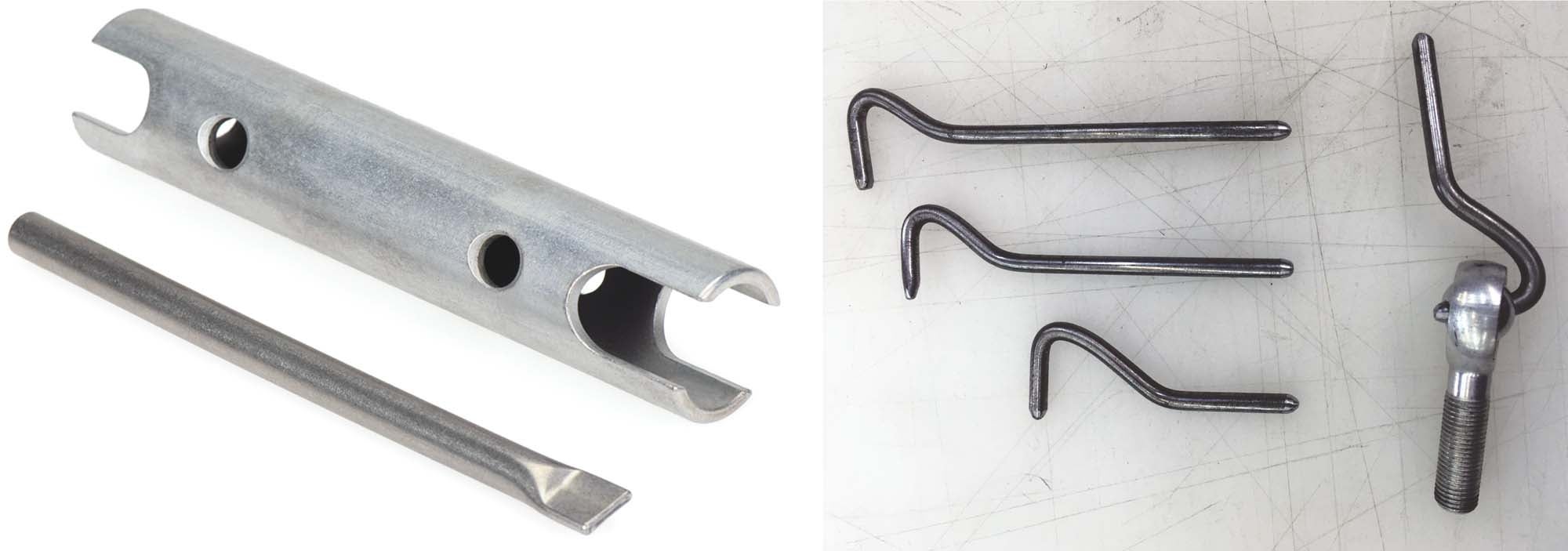
When aligning control surfaces, you’ll be fitting the surface multiple times in order to get everything lined up. Rather than use AN3 bolts for this, when building the RV-4, I made a set of fitting pins from 3/16-inch piano wire that are much faster and easier to install and remove. The pins are in the dogleg shape as shown in the photo. Similar to the Avery tool, an unused pin can be slid through a hole in the opposite end of the tool to act as a T-handle if you forego the socket-drive approach described above. This is not a new idea and you can see a variety of ideas for fitting pins online at forums like VansAirForce.net.
As noted earlier, one of the advantages of using rod ends as hinges is the ability to make sure the rotational axes of the rod ends are collinear. The next tool helps to establish this axis. It is comprised of a pair of drilled AN3 bolts (or whatever size bolt the rod end takes) that are also center drilled with a 1/16-inch or #40 bit.
For the end drilling operation, first file or belt sand the end of the bolt flat; otherwise the bit will wander. Clamp the bolt in your drill press and spot drill the end with a bit approximately the same diameter as the bolt, just enough to get the surface concave. This will prevent the smaller 1/16-inch bit from wandering. Go slow, using new bits and a small amount of WD-40 as cutting fluid to avoid breaking the bit.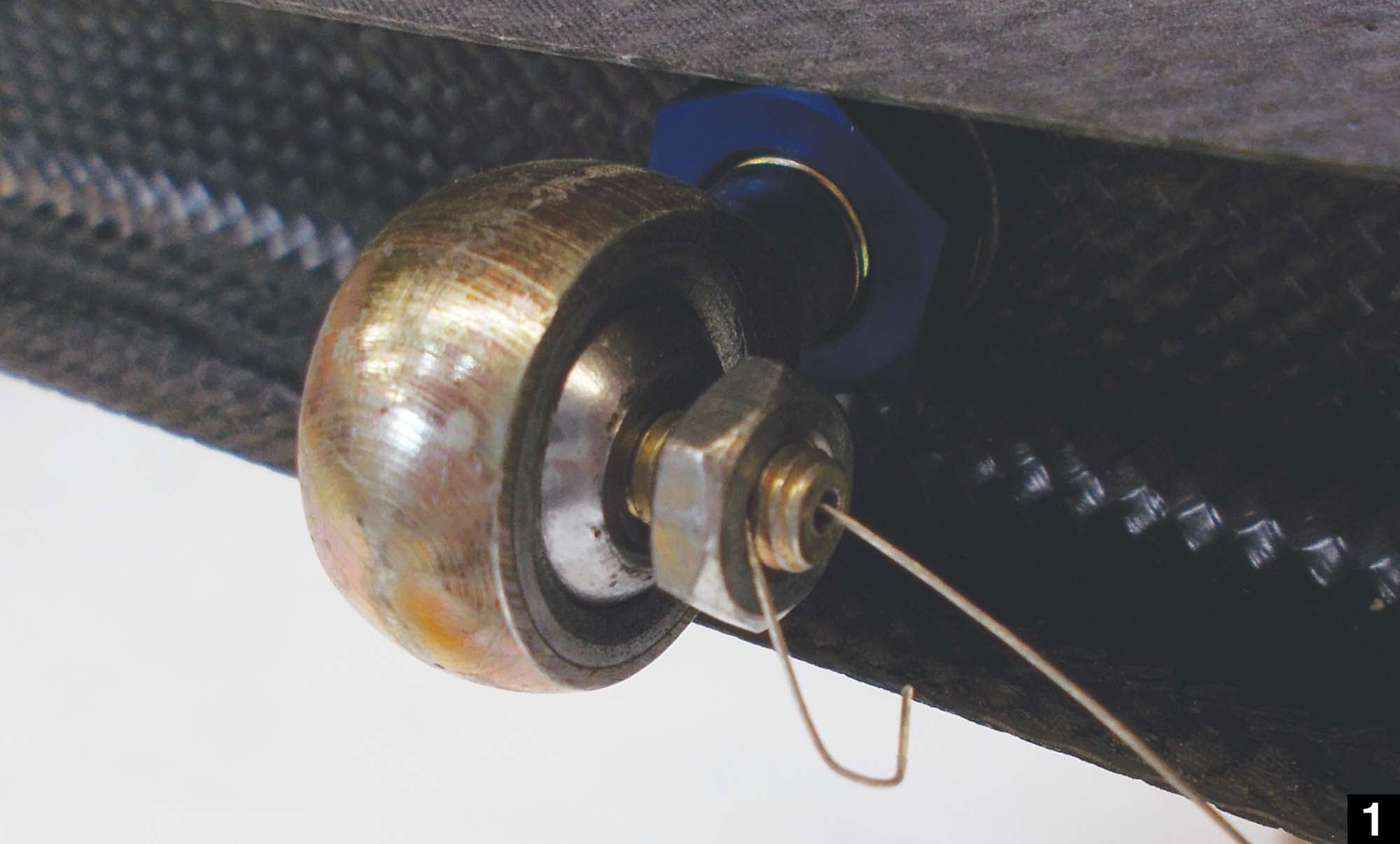
Step by Step
Follow these instructions and you should be able to establish a straight line through your rod ends.
1. Insert the first center-drilled bolt through the far left rod end and thread on a jam nut. Thread steel wire through the center of the bolt and out through the side hole, then (un)screw the jam nut until it holds the steel wire tight.
2. Run steel wire through the center of the rod ends and bearings.
3. Prep the far right rod end with the other center-drilled bolt and jam nut.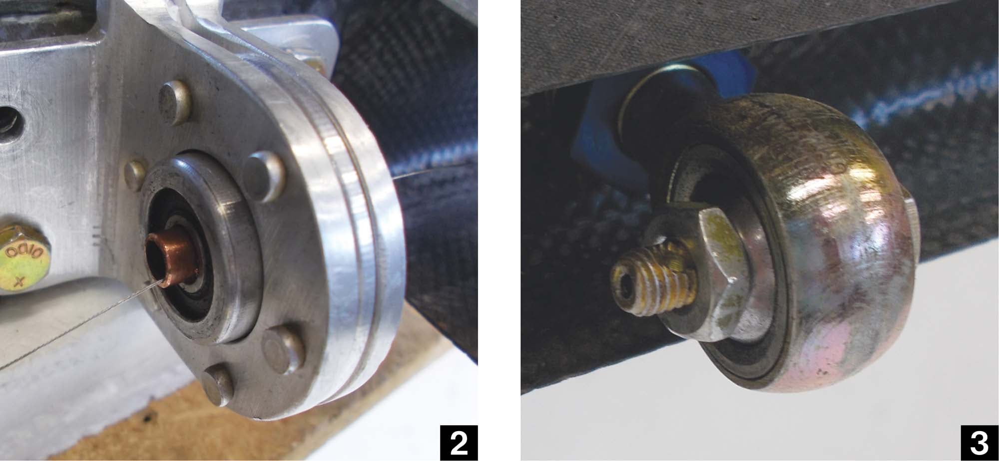
4. Pass steel wire through the bolt, pull as tight as possible by hand and tighten the jam nut to hold the wire in place.
5. To achieve maximum tension on the wire, spacer washers can be fabricated by slotting 0.062-inch-thick aluminum AN3 washers and inserting them between the head of the bolt and the ball of the rod end.
6. It’s difficult to tell from the oblique perspective, but the right ball end still needs to come out a half turn in order to center the wire in the middle bearing.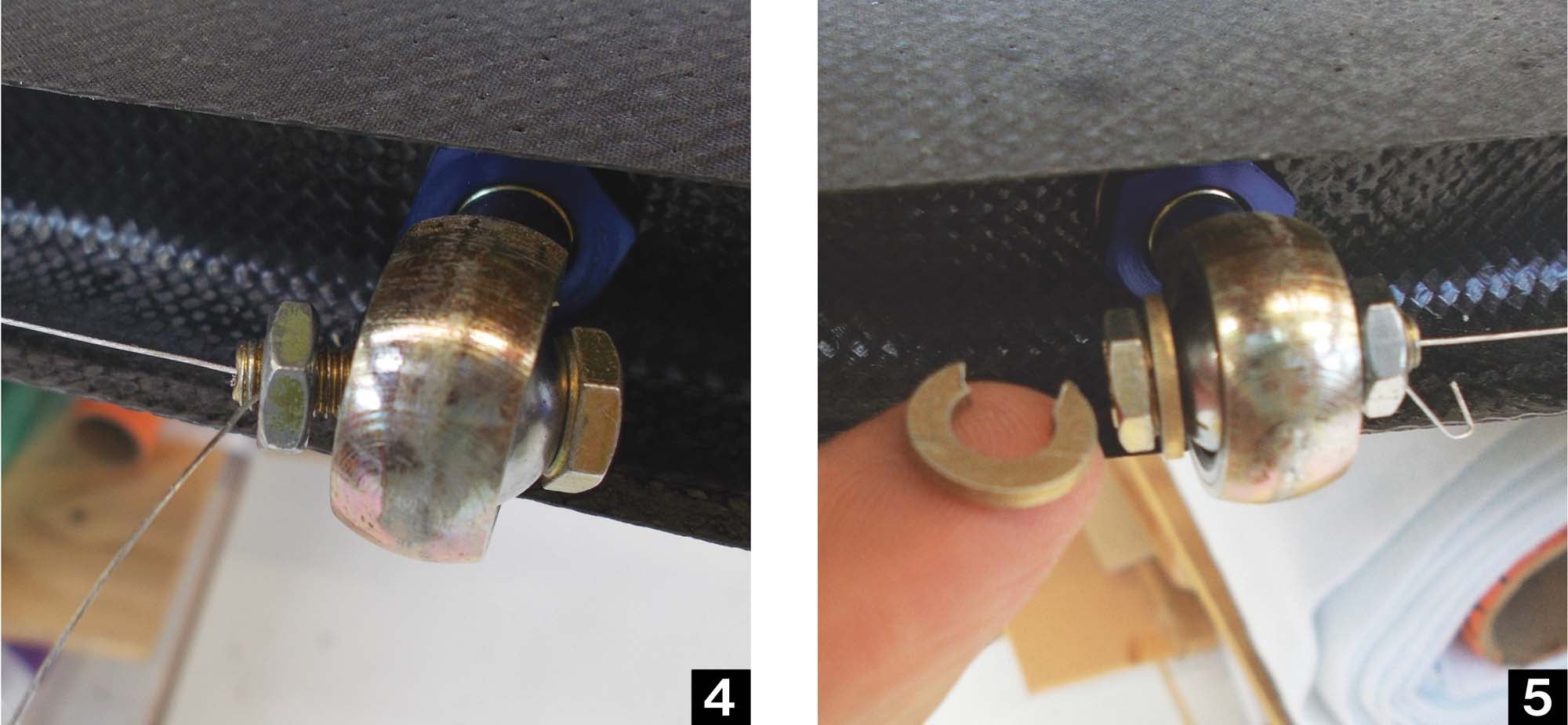
7. Once the wire is perfectly centered, the rod ends are marked with a small dot of red (left/port) or green (right/starboard) nail polish to indicate the orientation (up or down) of the rod end in case it needs to come out. Again, once final assembly is finished, the jam nuts should be tightened and marked with nut lacquer or torque striping to indicate they have been final torqued. I also use red and green nail polish to differentiate between left and right parts that are otherwise identical looking. 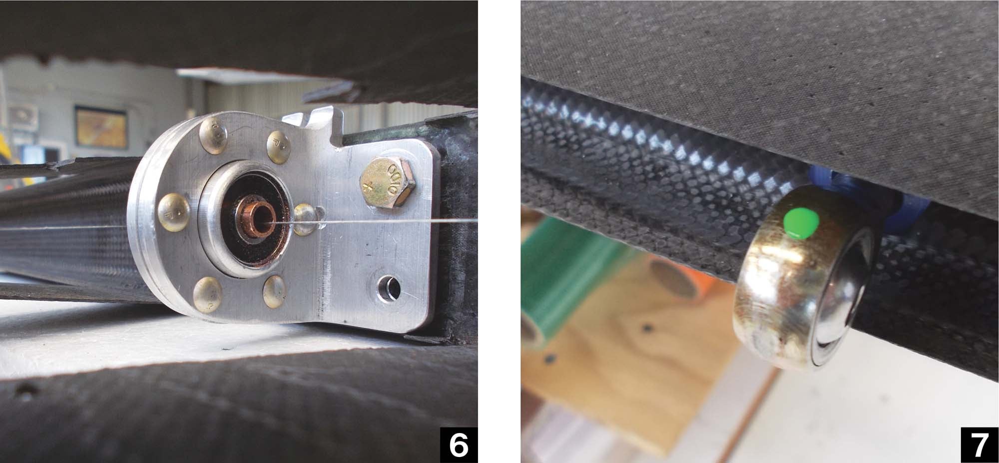


 Wordless Workshop")


