An airplane’s cooling system must keep the engine temperature within its operating range over the entire flight envelope and the entire range of outside air temperature (OAT) the airplane will encounter. This is not a simple task since both the amount of heat the engine must reject and the amount of airflow available to cool it vary dramatically depending on flight condition.
For airplanes with a relatively small speed range from stall to cruise, or airplanes where high-speed performance is not an important mission requirement, a fixed-geometry cooling system will work well. The inlets and outlets are sized to cool the engine properly at full power and low airspeed as is typical in a maximum-performance climb. In this situation, the engine is generating the maximum amount of waste heat, and the mass flow of cooling air through the system is at a minimum because of the low airspeed.
For a fixed-geometry set of inlets and outlets, the mass flow through the system is directly proportional to airspeed. As the airplane flies faster, more air will flow through the cowl. If the system is sized to provide sufficient cooling at minimum airspeed, rather than at any higher speed, there will be more cooling airflow than necessary. Since every bit of air that flows through the cowling exacts a drag penalty, the airflow that is excess to cooling needs causes an unnecessary drag penalty for that flight condition. The bigger the speed difference between climb and cruise, the more air coming on board at cruise will be excess to cooling needs.
In cruise, this situation is amplified because the airplane does not cruise at maximum power. Piston engine airplanes typically cruise at power settings between 65% and 75% power, and essentially all manufacturers quote cruise performance at 75% power.
So, for example, when a high-performance airplane that stalls at 60 knots and cruises at 180 knots is in cruise, it will have about three times the cooling mass flow available to carry away three-fourths of the heat that would be the case in a steep full-power climb. The drag penalty for this excess cooling flow can be large.

Variable Geometry
The way to reduce or eliminate excess cooling drag in cruise is to use a variable-geometry cooling system that can change shape to control the amount of air flowing through the cowling. We can do this either by adjusting the geometry of the inlet to control the amount of air it ingests directly, or we can adjust the geometry of the outlet, which controls how much air can leave the cowl and thus controls the total flow.
Inlets
Variable-geometry cooling inlets are rarely used as the intake for primary cooling air. For a typical engine installation with two inlets, one on each side of the spinner, it is difficult to integrate a mechanically simple variable-geometry inlet. For systems with a single inlet under the prop, it’s possible to use a hinged lower inlet lip to change the size of the inlet in flight. The Rutan Catbird use this type of variable-geometry inlet for cooling.
Openable scoops are also sometimes used to control the amount of secondary cooling airflow for oil coolers.
Outlets
The standard approach for giving the pilot control over the amount of cooling airflow is to use variable-geometry outlets. These can be designed to change both the size of the exit aperture and the air pressure at its exit. On such a system, the cooling air inlets are sized to provide adequate cooling air over the entire flight envelope. The outlets are sized to restrict cooling flow to the amount needed to cool the engine in cruise, and the variable-geometry feature is used to open up the outlets to enable greater cooling airflow at low airspeed and high power as is typical in climb.
Cowl Flaps
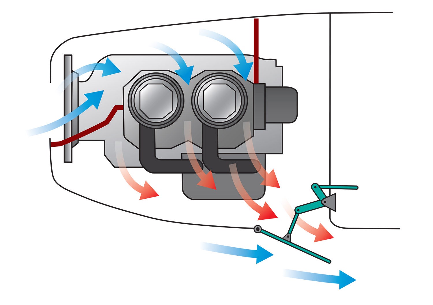
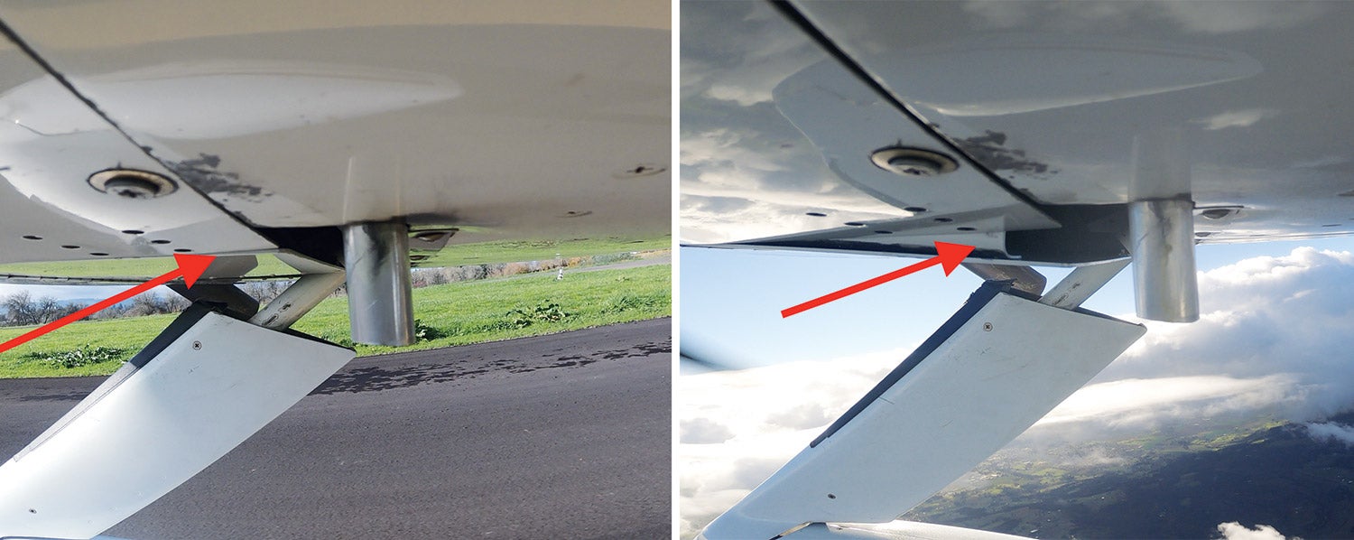
The most common form of variable-geometry outlet is based on the use of cowl flaps. A cowl flap is a portion of the outer lip of the outlet. It is hinged at its leading edge so that it can open outward into the external airstream.
Opening a cowl flap has two effects: It increases the size of the outlet aperture and it also deflects the oncoming external airstream outward from the skin of the airplane. Both of these effects work to increase the amount of cooling air flowing through the system. The larger exit aperture makes it possible for more air to exit the cowling for a given exit velocity.
The outward-deflected cowl flap acts as a dam to oncoming external flow. As the air negotiates the obstruction caused by the cowl flap, the air pressure on the forward-facing outer skin of the cowl flap increases and the air pressure behind the cowl flap decreases. This makes the external air pressure at the cooling air exit aperture lower than it would be without the deflection caused by the cowl flap. The lower air pressure at the cooling air exit increases the pressure differential between the high pressure in the upper plenum and the lower pressure at the exit. This pressure differential is what drives air through the cooling flow path, so increasing the differential increases the total cooling airflow.
Cowl flaps generate increased drag when they are opened. As we just saw, the air pressure on the forward-facing skin of the cowl flap is higher than the air pressure on its inner/aft face. While this pressure difference works to increase the cooling airflow, it also generates a net rearward (drag) force on the cowl flap itself. The flow behind the open cowl flap can also disrupt the flow over other components of the airplane that are farther downstream. It’s important to take the effect of the wake of the cowl flap and the exiting cooling flow into account when placing the cooling air outlets on the airplane to ensure that there are no serious detrimental interference effects with the cowl flaps open.
Airplanes that need variable-geometry cooling systems are typically higher-performance airplanes with high power-to-weight ratios to give them the high cruise speed they are designed to achieve. Because of this, they have ample power at lower speeds to overcome the extra drag of the cowl flaps, and the small decrease in climb performance it causes is an acceptable penalty to gain the cruise performance improvement the variable-geometry system can give.
Variable Flush Ramps
If the drag of opening a cowl flap is too much for a particular airplane design, an alternative is to use an inward-opening flush ramp to vary the size of the outlet aperture. These ramps are hinged at their aft edge and form the inner side of the cooing air exit path. Moving the ramp changes the distance between the forward edge of the ramp and the outer skin of the cowling, thus altering the size of the outlet aperture. The ramps open inward, so moving them inboard increases the size of the cooing air exit, and moving them outward reduces it.
Since the ramps are entirely inside the cowling and open inward, they never protrude into the outer flow and hence do not generate the same drag increase as cowl flaps do. The downside is that the ramps don’t produce a low-pressure zone at the cooling air exit to help pull flow through the system, so they are somewhat less effective than cowl flaps. Ramps are also harder to integrate because they need space to move inside the cowling.
Both forms of variable-geometry outlets can produce significant improvements in performance over a fixed-geometry system for high-performance airplanes with a large speed range between climb and cruise.


The article discusses a variable geometry cooling system for aircraft, I am intrigued. How does a variable geometry cooling system enhance aircraft performance and efficiency?