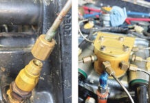
Does your preflight checklist include an item Fuel-Tank Vents-Check for Contamination or Blockage? If not, it should. The consequences of blocked fuel-tank vents can be serious, including collapsed fuel tanks and engine stoppage in flight. That will ruin your day.
Fuel-tank venting is probably something most builders take for granted, trusting either the kit-maker’s approach or commonly held beliefs on the subject. But there’s more to it than that.
Tank Vent Requirements
Fuel-tank vents serve specific purposes, including the following:
- Protect fuel tanks by equalizing internal and external pressure
- Provide a slight positive pressure to prevent siphoning of fuel
- Act as an overflow drain of fuel when fuel expands due to high temperature
- Allow fuel vapors to escape from the tank as the aircraft climbs as the air pressure decreases with altitude
- Allow air to enter the tank as the aircraft descends as the air pressure increases with altitude
- Allow air to replace the fuel volume in the tank as the fuel is burned by the engine.
- In addition, the FAA regulations (Part 23 Section 23.975) include the following requirements:
- Each vent outlet must be located and constructed in a manner that minimizes the possibility of its being obstructed by ice or other foreign matter.
- Each vent must be constructed to prevent siphoning of fuel during normal operation.
- The venting capacity must allow the rapid relief of excessive differences of pressure between the interior and exterior of the tank.
- Airspaces of tanks with interconnect-ed outlets must be interconnected.
- There may be no point in any vent line where moisture can accumulate with the airplane in either the ground or level flight attitudes, unless drainage is provided. Any drain valve installed must be accessible for drainage.
- No vent may terminate at a point where the discharge of fuel from the vent outlet will constitute a fire hazard or from which fumes may enter personnel compartments.
- Vents must be arranged to prevent the loss of fuel, except fuel discharged because of thermal expansion, when the airplane is parked in any direction on a ramp having a 1% slope.
The Basic Types
Aircraft fuel tanks may be integral with the structure, internal rigid tanks attached to the structure, or flexible fuel cells attached to or suspended from the structure. They may be made of steel, aluminum, composite or rubberized fabric. In all cases, the tanks are made as light as possible to withstand the fuel loads during flight maneuvers. They are not designed to withstand internal or external air pressure loads. Consider a small tank of 1 cubic foot. It will hold 7.5 gallons, which weighs 45 pounds. In a 4-G maneuver this fuel weighs 180 pounds and will exert a pressure of 1.3 psi on the floor of the tank. If the tank’s vent becomes blocked and a pump evacuates the fuel, the tank surfaces can be subjected to a pressure of one atmosphere or 14.7 psi, more than 10 times the amount of the maneuvering loads in our simple example. It is not surprising that fuel tanks can collapse under suction loads or be damaged by high internal pressure.
Fuel-tank vents are designed to provide a slight positive pressure in flight. This is mainly to prevent siphoning of the fuel. In the case of bag or bladder style non-integral tanks, the positive pressure also serves to keep the tank in place within the structure and to prevent collapse.
When aircraft are fully fueled on a hot day, the fuel in the tanks expands. To prevent damage due to internal pressure, fuel-tank vents also serve as an overflow drain, allowing the fuel to vent to a safe location outside the aircraft.
During climbs the air pressure decreases with altitude, so the fuel-tank vent must allow the fuel vapor in the tank to vent to a safe location outside of the aircraft. Conversely, during descents the air pressure increases with altitude, so the fuel-tank vent must allow air into the tank to equalize the pressure.
Finally, the fuel-tank vent must allow air to replace the fuel volume in the tank as the fuel is burned by the engine. While the previous functions serve to protect the tank or aircraft structure, this function is directly related to flight safety. Nobody wants to have a bad day when the engine stops in flight because blocked fuel-tank vents prevent fuel flowing to the engine.

Figure 2.
Examples of Tank Vents
Now that we understand what a fuel-tank vent must do, let’s take a look at some examples.
Figure 1 shows a very simple fuel-tank vent on an Aeronca Chief. It is simply a hole drilled in the fuel-tank cap. The tank is a rigid internal type mounted inside the fuselage ahead of the instrument panel. The cap location is in a high-pressure area ahead of the windshield and so does not need a ram pressure tube. A separate fuel level indicator is mounted on top of the glareshield. A variation on this fuel-tank vent on other Aeroncas, Taylorcraft, etc. has a level-indicating float wire protruding through the vent hole. All of these types of vent are susceptible to rain ingress and should be protected with a cover when parked.

Figure 3.
When the fuel tanks are located in the wings, the fuel-tank vent will typically have a forward-facing ram tube because it is located in a low-pressure area of the wing. Figure 2 offers an example on a Luscombe Silvaire.
High-wing Cessna aircraft with struts, such as the Cessna 150, have a slightly different system. The fuel tank cap(s) (Figure 3) have vents built into the body of the cap. In addition, there is a forward facing ram vent (Figure 4) underneath the wing behind the strut. In this position it is protected from impact ice. The vent is connected to the tank via a spring-loaded check valve that has a small hole drilled into it. The hole acts as a vent, unless there is a large enough pressure difference that the check valve opens, and also acts as an overflow drain for thermal expansion. This is why Cessnas drip fuel from this vent when the tanks are full.

Figure 4.
High-wing Cessnas such as the Cardinal (Figure 5) with non-strutted wings typically have their fuel-tank vents in the wingtip outboard of the ailerons facing aft. A variation on this latter type of vent is the Glasair version, which breathes through a hole located in the outboard rib of the aileron.
Many low-wing aircraft use a simple metal tube protruding from the lower wing surface. The bottom of the tube is cut at 45 facing into the airstream to provide positive pressure to the tanks. This type of fuel-tank vent is used on aircraft such as Beechcraft Bonanzas (Figure 6), Piper Cherokees (Figure 7) and Arrows, and Mooneys. The Bonanza shown has auxiliary tanks, thus one fuel vent for each tank. Late model Mooneys certified for known ice have different fuel-tank vents that will be covered later.

Figure 5.
The 45 cut tube type of vent is also used on aircraft certified for known ice; however, they are heated. Look closely at aircraft such as the Beechcraft King Air or Baron, and you will see a fine resistive wire wrapped around the tube. This provides heat to keep these fuel vents from becoming blocked from ice.
On low-wing aircraft, instead of the 45 cut tube, another way of providing positive pressure is to curve the tube so it faces into the airstream. An example of this is on the bottom center section of the wing on a North American Harvard Mk IV (Figure 8). Although it is a bit hard to see, there is a deflector on the aft side of the curve for aerodynamic flow control.

| Figure 6. | Figure 7. |

Figure 8.

Figure 9.
On the Diamond DA-40 (Figure 9), the fuel vents are simply two tubes inset into a round removable panel of the wing. They are located about half chord and 7 feet inboard of the wingtip. The tubes extend about 1⁄16 inch below the skin surface. The smaller (forward) tube is a capillary type that serves as an overflow fuel vent and a supplementary vent if the main vent becomes blocked. The larger (aft) tube is the main fuel-tank vent and is fitted with a check valve to allow air into the tank but to prevent flow to the outside.
Nix the Ice
The protruding vents discussed so far are susceptible to blockage from impact icing. Aircraft that regularly fly in icing conditions usually feature heated vents, submerged vents or both. Of course, electrically heated fuel vents will prevent ice blockage, but only if they are turned on and the electrical supply does not fail. A submerged vent is inset below the surface of the airplane skin usually in the wing. These do not have an exposed surface that ice can build up on and so are less susceptible to impact ice. They are usually located far enough aft of the wing leading edge that they are not affected by ice run back.

Figure 10.
On the Piper Malibu Matrix (Figure 10) the submerged vent is formed in an oval removable panel mounted near the outboard ends of the wings close to the leading edge. The submerged section is about 2.5 inches long by 3 inches wide and is inset ⅝ inch. The transverse section is approximately rectangular, while the longitudinal section has a radiused leading edge, a curved top and a radiused trailing edge with the vent tube inset into the trailing edge wall. Similar vents, differing slightly in dimensions, are found on the Piper Seneca and Navajo. The performance of this style of fuel-tank vent is discussed in Reference 1.
The Beechcraft King Air (Figure 11) has an interesting combination of fuel-tank vents. They are located under the wing outboard of the engine nacelles at about mid-chord of the wing. One vent is the previously mentioned 45 cut tube type with resistive wire heating. The other vent is a rectangular submerged type about 1.25 inches wide by about 4.25 inches long by about a half-inch deep. The floor of the ramp has a shallow angle at the leading edge and a steep angle at the trailing edge. The vent tube is inset into the trailing edge wall slightly offset from the centerline. Both vents are teed together before they go to the fuel tanks.

| Figure 11. | Figure 12. | Figure 13. |
Most pilots are familiar with the NACA flush inlet type vent, which features straight or S curve shaped side walls and an angled flat floor ramp. It is commonly used as a cabin vent, engine induction air inlet, oil cooler inlet and various other vents that require a low-drag profile. The NACA flush inlet type vent is also used as a fuel-tank vent on aircraft ranging from small single engine general aviation aircraft to transport category jets. Figure 12 shows a NACA flush inlet type fuel vent on the winglet of a Lancair IV, just above the top gold stripe. On Lancairs without winglets, the vent is on the lower surface of the wingtip. Figure 13 shows one on a Lancair ES. The Cirrus SR20 (Figure 14) also has a NACA flush-inlet type fuel vent underneath the wings near the tip. Note that the fuel vent hole is inset into the aft floor of the ramp above the lip and is almost hidden from view. The performance of this style of fuel-tank vents is discussed in Reference 3.
Getting back to Mooneys, on models such as the M20R (Figure 15) with the TKS anti-icing system, the fuel-tank vents were changed from the 45 cut tube type to the NACA flush inlet type vent. The vent is 11⁄4 wide by 35⁄8 long positioned about 8 inches behind the leading edge of the wing. It is located about a quarter of the way inboard from the wingtip. It differs from the geometry specified in Reference 3 by having the vent tube protrude from the rear wall into the recessed area.

| Figure 14. | Figure 15. | Figure 16. |
Compared to the other fuel vents discussed, Cessna 300 and 400 series twins have a rather unusual fuel vent (Figure 16). The fuel vent tube is flush with the skin of the wing near the leading edge both inboard and outboard of the engine nacelles and the tube opening is protected by a formed sheet metal strip riveted over the opening. The strip has a dome shape about the size of your thumb formed into it with the aft end being open. The dome shape protects the fuel vent from impact and runback ice. The location of the vent near the leading edge probably provides a positive vent pressure even though the opening faces aft. This effect is more pronounced at high angles of attack.

Figure 17.
And, finally, my favorite fuel-tank vent, a complex and beautiful aluminum casting used on the Grumman S-2 Tracker, a Navy anti-submarine warfare aircraft. The fuel-tank vent is mounted on the outboard side of the engine nacelle about mid wing chord (just above the black hose shown in Figure 17). It features a streamlined inertial separator in front of the vent opening. Considering the operational environment (low level patrol over the ocean), this separator would prevent salt spray from entering the vent and provide a mast for ice to accumulate on, thus protecting the vent opening.
What’s It Mean To You?
Homebuilt aircraft have an interesting variety of fuel-tank vents. However, space does not permit a discussion of them except for some of the Van’s series. RV-6s, -7s and -9s use an AN832-4D bulkhead fitting modified with a 45 cut mounted just aft of the firewall outboard corners. Van’s RV-8s are similar to the North American Harvard example, though the tubes are smaller and located in the cooling air exit duct in the bottom of the fuselage aft of the firewall. Curved tubes are also used on RV-10s but protrude through the wingroot fairings.
In the late 1940s, the National Advisory Committee for Aeronautics (NACA) did extensive research into the geometry and performance of fuel-tank vents. At the time, bag-type flexible fuel cells were being introduced into transport aircraft, and it was found that without positive pressure inside the fuel cells they could collapse and cause fuel to vent overboard. Clearly an undesirable situation! References 1, 2 and 3 (below) summarize the various geometries investigated and their ability to maintain a specified positive fuel cell pressure during icing conditions and various speeds and angles of attack. None of the configurations tested were immune to the effects of icing, and they all lost some ability to maintain positive fuel cell pressure. The S-curved sidewall NACA flush inlet type vent had the best performance of the geometries tested. The three types of flush vents described in these research papers are featured extensively in the examples above, especially those which may fly in icing conditions.
Recommendations for Homebuilders
Consider both the functional and regulatory requirements. Even though Part 23 (Reference 4) does not specifically apply to homebuilt aircraft, the requirements make sense and should be used for guidance. If you are building a kit, review the designer’s provisions for fuel-tank vents and determine if this design is adequate for your mission. If the vent opening is large enough for insects to enter, consider including a “bug screen” on the opening or slightly inside the tube where it can still be inspected and cleaned. If it is not possible to include a bug screen, consider vent covers or plugs similar to pitot tube covers when the aircraft is parked. There have been several cases of engine stoppage in flight due to the fuel vent tubes blocked by insects.
If there is a possibility of flying in icing conditions, and even under VFR rules it is possible to get trapped in such conditions, consider heated vents, submerged vents or a combination of both. Think about the tubing routing between the external vent and the fuel tank to ensure that there is no low point where moisture can collect and possibly freeze. Finally, add an item to your preflight checklist: Fuel-Tank Vents-Check for Contamination or Blockage. You’ll be glad you did.


