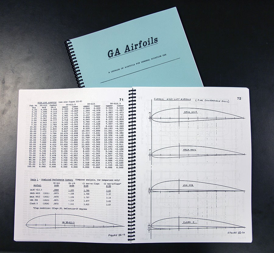
By inclination and training, engineers are curious people and incurable, tenacious problem solvers—especially when the object of their obsession is personal. For Harry Riblett Jr., it was airfoils. A mechanical engineer, he spent more than a decade optimizing 98 NACA profiles for use by general aviation aircraft and cataloged the results in six editions of GA Airfoils. Until he scratch-built a Starduster Too in the 1970s, his knowledge of, and interest in, the shapes that generate lift didn’t extend beyond ground school. But he wasn’t happy with the biplane’s performance. “It did OK on the top end, cruising at 130 mph on a 150-horse Lycoming, but I was disappointed with the takeoff and rate of climb,” he said. Sharp corners in his avuncular tone hint at what motivated his quest for knowledge: “My twin brother’s Piper PA-20 Pacer would beat me off the ground every time.”

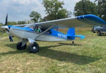
This Bearhawk wing, designed by Bob Barrows, uses a Harry Riblett airfoil to provide good stall characteristics and short field performance.
Riblett and his twin, Dave, were born in 1929 east of Los Angeles in the small town of Monterey Park. Their parents, Anna and Harry, Sr., shortly thereafter moved the family to Beaver Falls, northwest of Pittsburgh, where the twins grew up with their brother, Richard, now a corporate pilot, and sister, Francis, a physical therapist. Still close, many of the family members built houses on their father’s 16 acres. In 1946, Harry, Sr. opened a Kaiser-Frazer automobile dealership and a GI-Bill flight school in Wilmington, Delaware. Called Superior Skyways, the school had two Cessna 120s, two 140s, a 170A, a PT-19, and a PT-17. “I flew them all,” Riblett said. In addition to earning his commercial pilot certificate at 17, he worked on planes and the cars at his dad’s dealership.
For reasons he can’t explain, Riblett earned a degree in business administration from the University of Delaware. Then he joined the Navy and spent three years in the Mediterranean, directing fighters from the combat information center aboard the USS Des Moines, a heavy cruiser that was the flagship of the Sixth Fleet. Once out of the Navy in 1955, he got married, built a house and started a family. His oldest son, Allen, born in 1954, is a civil engineer in Virginia; Gail, born in 1957, is a lawyer; and Mark, born in 1962, is a mechanical engineer. There are also six grandchildren.
After working for several months as an accountant, Riblett enrolled in night classes at Philadelphia’s Drexel University and earned his degree in mechanical engineering. During the day, he worked for the All American Engineering Company, which was developing a land-based catapult and arresting gear system for the Marine Corps called SATS, which stands for short airfield tactical support. “They gave it up in 1966 and I got laid off,” Riblett said. “I went to Hercules, an S&P 500 chemical company in Wilmington, and worked on [a proto-polymer printing plate] until my retirement.”
That he would one day build an airplane was a given, Riblett said, and his Starduster Too won an award at the 1973 Valley Forge fly-in. It had a NACA/M-6 airfoil, a thin low-drag design favored by racers like the Granville brothers. It was created by the National Advisory Committee on Aeronautics (NACA) and its chief of aerodynamics, Max M. Monk, a German with doctorates in physics and math, who was recruited for the job after WW-I.
Best known for his thin airfoil theory, in 1922 Monk separated an airfoil’s shape at the mean camber line to more easily model its behavior at varying thicknesses, a leading design technique until the development of laminar flow airfoils in the 1930s. To conduct this research, Monk built a variable density tunnel (VDT), which added altitude to the testing environment. In operation between 1922 and the 1940s, the VDT is the source of most NACA airfoil data. Still standing at NASA Langley, it’s now a national historic landmark.
Two decades of airfoil research essentially ended with WW-II. NACA usually published the results of this work, but “the scattered nature of the data and the limited objectives of the reports have prevented adequate analysis and interpretation of the results,” wrote three NACA engineers in 1945. In NACA Report 824, Ira H. Abbott, Albert E. von Doenhoff, and Louis Stivers “summarized these data [to] correlate and interpret them as much as possible.” Abbott and von Doenhoff continued that work on their own, publishing the Theory of Wing Sections: Including a Summary of Airfoil Data in 1949. (It’s still in print. Amazon sells the 693-page paperback, unabridged and corrected, with 350 pages of tables and a new preface by the authors, for $14.65.)

Riblett’s book—GA Airfoils—represents a lifetime worth of work improving and tweaking the NACA airfoils. Designers can find coordinates for these improved airfoils. EAA still prints it and you can order a copy online from EAA for $17.95.
Riblett called it “the bible of airfoil design,” and it was the starting point of his autodidactic airfoil effort. As he read and learned, it appeared that NACA never finished its work. Then he learned that the work was never intended to design airfoils for actual use; they were “merely wind tunnel test specimens that investigate the effect of changing various airfoil parameters on airfoil performance.”
Discussing the shortcomings of these test specimens, Riblett seamlessly transitioned to the concise engineering vernacular of his book. The story of each airfoil’s performance is written in the sinuous plots and tables that reveal its “see-sub-l, see-sub-d, and see-sub-m” for combinations of velocity and angle of attack (AoA) up to stall. Careful reading (and listening) teaches that C1 is the coefficient of lift, Cd the coefficient of drag, and Cm the pitching moment. It was the last coefficient—pitching moment—that became Riblett’s primary focus.
“NACA airfoils are mid-loaded,” he explained, meaning the lift is evenly distributed across the chord, which leaves the front end susceptible to airflow separation at high angles of attack. As a result, the NACA airfoils “have an unnecessarily high see-sub-m.” The initial camber angle at the nose of the NACA airfoils contributes to airflow separation and, consequently, the high pitching moments. To correct this problem, Riblett moved the loading forward and changed the initial camber angle to 12 degrees. As a result, all of his airfoils are soft-stall airfoils and there is no leading edge separation at high angles of attack.

Riblett is survived by his wife JoAnn, two sons who are engineers, and a flock of grandchildren. His older son inherited Riblett’s Starduster when the father gave up his medical certificate.
Learning this took patience. Without the resources to build his own VDT, Riblett had to wait for a viable and affordable alternative. The pieces came together in the early 1980s: Dr. Richard Eppler’s airfoil design and analysis program was translated into MS-DOS, and Riblett got the first copy of it for use on his personal computer. (The Eppler program, modified by another autodidactic airfoil designer, John Roncz, to correct for compressibility, may be downloaded at no cost from Public Domain Aeronautical Software, www.pdas.com.)
Plugging each airfoil’s ordinals into the Eppler program, Riblett ran repeated NACA velocity and angle of attack combinations because different data sources don’t provide congruent data, he said. “The computer is accurate to generally within 5% of wind-tunnel data.” Each computer test averaged an hour, as did every subsequent trial-and-error test that measured the effectiveness of his changes. Ultimately, he improved 98 NACA airfoils in three thicknesses, 12%, 15% and 18% of chord. They are divided into four series: GA30, GA35, GA37 and GA40. The figure represents the position of maximum thickness in percent of chord, and the last three series are laminar flow airfoils.
As he was creating his airfoil catalog, Riblett twice visited NASA Langley to encourage the organization to finish what NACA had started, showing his work as an example of what was possible. “They didn’t want to talk to me,” Riblett said, “so I decided to publish them myself. I donated my book and the copyright to EAA in 1997 [on the condition that] they would keep it in print for perpetuity.” In 2001, he received the Dr. August Raspet Memorial Award “for outstanding contributions to the advancement of the design of light aircraft and the Experimental Aircraft Association.”
Until a triple bypass slowed him down four years ago, Riblett made the annual pilgrimage to Oshkosh, where he held airfoil forums. Roughly 24 aircraft, such as the Kitfox Speedster, Nexus Mustang, Dream Tundra and an amphibious twin called Gweduck now fly because of his airfoils. So does the Bearhawk Patrol and Bearhawk LSA. (See page 14 in this issue.) The designer, Bob Barrows, says he learned about Riblett airfoils after he designed and built the four-seat Bearhawk in the early ’90s. Buying the book and studying its airfoil selection, Barrows chose the GA30-4135. “It’s a turbulent-flow airfoil,” he said, perfect for “backcountry flying, with good stall characteristics that could put up with a little deterioration of the wing smoothness” from mud or bugs.
“The airfoil does what Riblett claimed it would,” Barrows said. “It has very little pitching moment, so the trim changes are very minor, and the stall characteristics are great.” He says they’re way better than the USA 35B airfoil used on every member of the Cub family from the Taylor E-2 to the Tri-Pacer. “I wish more people weren’t afraid to try something new,” Barrows said. “[Riblett] had a set of airfoils that will actually save a lot of people’s lives,” referring to a backcountry killer, the moose turn stall. Related to a turn from base to final, the moose turn puts a pilot low and slow, while watching the target below. Unconsciously applying some opposite aileron to keep the inside wing out of the pilot’s field of view is all it takes to flip the Cub on its back and into a spin, Barrows says. A Riblett airfoil’s soft stall and low pitching moment prevents this hair-trigger response to uncoordinated, inattentive flying.

Riblett built on the works of others, notably Richard Eppler, to come up with his own airfoil designs. He achieved results not found with the standard NACA catalog designs.
Barrows checked with Riblett before building any ribs. After hearing the airfoil’s mission, Riblett asked why he didn’t pick the 6% camber. “That was the thing about Harry,” Barrows said. “You could call him up and discuss things. I explained that with the Patrol’s great big flaps, I’ve got all the camber I need on takeoff and landing, and he agreed with me. And then Riblett went the extra mile. The 13.5% thickness ratio wasn’t in his book, so Riblett ran the numbers on his computer and sent Barrows all of the points. “The airfoil has been great!” Barrows said.
Barrows was not the only designer who called Riblett to discuss airfoils. Just before publishing the sixth edition of his book, GA Airfoils, Riblett got a call from a BD-5 pilot named Farmer, who didn’t like the airplane’s wicked stall or the time it took to get off the ground. The BD-5’s NACA 64-212 airfoil “has a relatively low lift coefficient and an extremely sharp stall break, a clear example of an unwise choice,” Riblett explained. Because the plane was already flying, the easiest fix was to re-profile the wing’s top surface with foam and glass. Riblett cranked out a top surface profile for Farmer (and later many others), and it worked fine. It’s in his book on pages 119 and 122.
On occasion, Riblett was a proactive consultant. Reading about the 1994 crash of an American Eagle ATR-72 near Roselawn, Indiana, he wrote the NTSB several letters that offered an explanation of the ice ridge that developed on the wing at a specific cord position. “It’s an anomaly with the NACA 430xx airfoil; negative pressure peaks at the 9% chord position,” he said. “Nothing happened. I offered my assistance and they didn’t want it.”
Riblett was a man with many hobbies, and since finishing his book, he’s restored a number of old cars, including a 1929 Model A Ford Huckster Wagon, and built a railroad pump car from 1890 drawings. Ever the problem solver, he replaced the gear drive with a chain and used modern ball bearings to make it easier to pump. In his garage was an unnamed airplane he designed decades ago, a single-seat, tube-and-rag, high-wing pusher with folding wings and tricycle gear. “It’s one of those things that will never get finished,” he said wistfully.
When getting a medical certificate proved too challenging, Ribblett gave the Starduster to his oldest son, who flew it for a decade before his health forced him to sell it. Despite it being the inspiration for his airfoil adventures, he never changed the Starduster’s NACA/M-6 airfoil for one simple reason: “It was too much work.”


Scott, I tripped over your article about Harry Riblett. Nicely done and lucky you to have known him. We’re in the midst of designing a single place tapered low wing, aluminum speedster to use as a West Coast get-around plane. The idea is to avoid the commercial flight experience, fly to San Diego in one hop and to Puget Sound in one day with one fuel stop. My friends have scattered far and wide. We’re set to start building this summer. Harry’s GA37-A315 profile is the best match. Harry used to provide faired outlines of specific cord lengths and I’m wondering if you know of anyone who can provide this service today. There are going to be 15 of these sections including ribs 3″ apart for the wing walk and I shiver at the thought of doing it by hand. Any ideas?
Thanks, Lauren Williams
12 N. Napa Dr.
Petaluma, CA 94954-1331
petalumatrolley@sbcglobal.net
707 763-7366
Hey Lauren,
There seems to be a number of spreadsheets and scripts available to generate Riblett airfoils. The links in one of the posts (by @Norman) on the following site may be especially interesting:
https://www.homebuiltairplanes.com/forums/threads/riblett-ga-30u-613-5-airfoil-how-good-is-it.26612/ – especially:
https://www.homebuiltairplanes.com/forums/threads/perl-script-for-riblett-airfoil-generation.20794/
Alternatively, (some code hacking required and it may not provide any significant advantage) I wrote a script for MoI3D a few years back that might be capable of being adapted or extended. It really depends on how the thickness distribution and mean camber line was defined by Harry. The conversation on the above page alludes to the fact the raw, un-cambered thickness distribution is defined in a similar or identical equation as that used by the (earlier) NACA airfoils – but I’m very happy to be corrected:
http://moi3d.com/forum/lmessages.php?webtag=MOI&msg=7265.21
If it can be, the benefit of adapting the MoI3D script would be this: You would define root and tip airfoil sections – and for ease of manufacture, tweak the T.E. thickness coefficient of those two sections until achieving a constant T.E. thickness along the entire span. Then, loft between those two sections to create the skin and finally, slice through the finished loft at whatever rib interval your project requires. That final step neatly takes into account any washout, tip section fore-aft position and tip section variation vs root section.
Due to time commitments, I’m unfortunately unlikely to be able to help if it requires any large-scale rework, but otherwise happy to add it to the list of jobs to get around to. Otherwise, feel free to hack away at the script. If you do, please re-publish it on the MoI3D forum. And either way, do let us know the method you ultimately use!
All the best, Hamish