The best way to go faster is by drag reduction. Drag reduction is far better than other methods from a cost benefit perspective because you get free speed or increased mileage—well, relatively free when compared to touching your propeller or engine. Both of those tend to be very expensive. Drag modifications, on the other hand, tend to take more time and effort than money. A 27% reduction in total airframe drag produced about a 25-mph increase in my top speed, or about 22% lower fuel burn in cruise.
I am frequently asked what mod did the most good. That’s difficult to answer because two different planes rarely start at the same point of total airframe drag, and their speeds may be different as well, so the mod will produce slightly different gains on each plane. If you put retractable gear on a tumbleweed, it probably won’t make much difference.
Also keep in mind that the faster your plane flies, the more important drag reduction becomes. Fairing a rotating beacon on a 100-knot plane will only give you about 0.1 knot of increased speed, whereas on a 200-knot plane it will produce about a 2.0-knot increase, and on a 250-knot plane it will produce about 5.5 knots. If you fly a plane that cruises pretty fast already, you should be interested in reducing drag.
Are You Flying a Cactus?
The easiest thing to do is to walk around your plane and look for anything that sticks out into the airflow. Each item that sticks out will cause drag, so the more of them, the greater the drag.
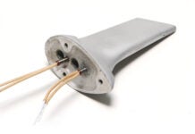
Antennas are cylindrical, which are draggy by their shape. The drag coefficient is about five times greater than a turbulent airfoil and about 50 times greater than a laminar one. So what to do? A straight antenna at 300 mph IAS takes about 3 hp to pull it through the air, and a 60-degree rake angle decreases the antenna’s drag by about 85%. However, an antenna inside a wingtip produces no additional drag. The transponder is the only antenna I have mounted outside, and it’s in dirty air.
Rigging
One thing that has a significant effect on airframe drag is rigging. When I first built my RV-4, I thought I was careful; however, when I started trying to go faster, I rechecked all my rigging again and was surprised to find out it wasn’t as good as I thought.
When you have a heavy wing, it’s probably because something isn’t quite right. Now, you can easily just increase the drag on the opposite wing, but finding out why it’s heavy and fixing the problem will result in lower total airframe drag. As an example, when I rechecked my original rigging, I found that both of my aileron cuffs were hanging down into the airstream on the high-pressure side of the wing. So, I remade the hinge brackets to position them within the proper airfoil. This may not be a problem with some of the kits today, but it’s still worth checking.
The original metal gear leg fairings were replaced with composite pressure-recovery fairings. Lamb tires were installed for reduced size and weight, along with very small pressure-recovery wheelpants.
Wheelpants and Gear Leg Fairings
Another area of common drag is the wheelpants and gear leg fairings. These can be very big trim tabs when not properly installed, which then requires offsetting drag to get the plane to fly straight.
For the gear leg fairings on an RV, you can secure them to the gear leg by clamping them at the top, heavily waxing the gear leg (before you put on the fairing), and putting in a little expandable foam between the front of the gear leg and inside the fairing on the top and bottom so it will support flight loads after it sets up. You don’t want the foam to stick to the gear leg, so you can adjust the fairing if necessary.
The next step is to use any flowing material that will leave a trace. Put a dot on the leading edge of the fairing and go fly. It should flow around both sides of the fairing and end up trailing off the back edge in the same spot. I used watercolor tempera paint mixed thick into 90-weight oil, and with a little trial and error was able to come up with the lowest drag position for the gear leg fairing. I then made interface fairings to maintain the gear leg fairing’s position.
Back in the mid 1990s, I removed Van’s original metal gear leg fairings and replaced them with composite pressure recovery fairings that were designed by John Lynch of JL Design in Santa Paula, California. These were carefully positioned for the lowest amount of drag using the watercolor tempera paint and 90-weight oil procedure.
Lamb tires were installed for reduced size and weight, along with very small lightweight two-piece pressure recovery wheelpants from Klaus Savier of Light Speed Engineering. The wheelpants have minimal tire exposure and are very tight around the tire opening for reduced drag.
I added a fairing to the tailwheel, and for racing I used an even smaller fairing with a Rollerblade wheel and no steering cables.
A fairing was added to the tailwheel. For racing, an even smaller fairing was used with a Rollerblade wheel and no steering cables.
These things resulted in a 6-mph increase due to additional drag reduction. I believe the most beneficial mods were redoing the wheelpants and pressure recovery gear leg fairings, and properly shaping and fitting the interface fairings. I may have had pretty effective trim tabs for my original gear leg fairings, but this demonstrated that this is an important area to get right.
Canoe Fairings and Empennage Gap Seals
Canoe fairings were made in 1997 and installed on all hinge brackets. These were a low-drag, laminar-flow shape designed by John Lynch. They are easy to install and only having to be taped on with double-sided tape. Later, I read a September 2005 article in Flying magazine by Peter Garrison called “Shelling the Air Snares” that confirmed this to be good science. The reason was based on drag:
Dynamic pressure sq. ft. (of the object) drag coefficient TAS in fps divided by 550 ft-lbs-sec / hp propeller efficiency (using 1.35 for the drag coefficient).
When you run through the formula, the total of the unfaired hinge brackets may require 2.4 hp at 220 knots. Faired hinge brackets, using a drag coefficient of 0.045, require about 0.1 hp at the same speed. Therefore, 2.3 hp is put into thrust, which under these conditions is about 1+ mph increase in speed. This exercise is for the truly fanatic.
Canoe fairings were installed on all hinge brackets with double-sided tape. The low-drag, laminar-flow shape was designed by John Lynch.
In addition to the canoe fairings, I also added the empennage gap seals that Dick VanGrunsven recommended in one of his RVator issues. The product I used is available from wingsandwheels.com and is listed under tapes and seals. Clear instructions for application are also available on the website. Van’s testing revealed an increase of about 1.5 mph or so when you do the entire empennage. This is just a taped-on addition of speed. You cannot use this technique on the RV-4 or similar ailerons.
Under the Cowl
Remove the cowl and take a close look at your system installations. Examine the airflow from the cowling inlets to the cooling air and exhaust outlet. Anything that is in the way of the airflow is increasing the cooling drag. Remember the cactus. This even applies to having spark plug wires that run perpendicular to the plenum airflow on top of the cylinders as well as heaters, scat tubing, hoses, wiring, and sensors that run within the pathway of the exit air under the cylinders.
Upper baffles on the cylinders fine-tune the airflow for optimum CHTs. They are sealed with a small amount of RTV and are adjustable.
These are small things, but they all add up. If you don’t need it, for instance a heat muff in the summer, remove it and your engine will run cooler, too. If you can reroute things like scat tubing from out of the airflow, reroute them. Run other things tight against the oil sump or outside the intake and exhaust tubes. The goal is to have the path of least resistance to any flowing air.
Think of water in a river flowing over boulders and then as it flows over a smooth sandbar. In the first case it is very turbulent and has lower velocities. The later is very smooth with higher velocities. Air is similar, just not as dense. The ultimate goal will be to use the least amount of air mass to cool the engine and then be able to reaccelerate it as much as possible to free-stream velocity.
NACA says that 30-46% of total airframe drag is from cooling drag. A cooling system that is well designed can be as low as about 5%. All garlock or rubber baffles leak, and poor baffling can produce greater than 50% of the total cooling drag. By closely looking at your baffling, you will be able to identify areas of gaps, holes, seams, and exits. All of these are areas that needlessly increase cooling drag but are easily addressed, sometimes as simply as by using RTV.
According to NACA, 30-46% of total airframe drag is from cooling drag. A cooling system that is well designed can be as low as about 5%.
You can become more creative with your baffling as you try to cool your engine with the least amount of flow-through air. You can also place upper baffles on your cylinders and direct the air where you want it to go. The upper baffles are sealed to the engine and cylinders with a small amount of RTV as in the photo, and the inlet areas are adjustable to each cylinder’s need for whatever CHTs you want.
Interestingly, as you cruise faster due to lower drag, you will have greater mass flow, and with an upper plenum you will have an even greater delta p across the cylinders, which will cool your engine even more with lower cooling drag. Or, if you cruise at the same speed, you’ll burn less fuel, make less power, produce less heat, and your engine will still be cooler.
I have run the AirVenture Cup race at 500 feet agl, at WOT, max everything, and have only seen 360 F on my CHTs, which also happens to be the temp I see when I climb from our 600-foot runway to 17,500 feet at maximum rate. A well-made cooling system has many benefits other than just lowering drag.
Three pieces of 0.020-inch aluminum were used to smooth the flow of cooling air exiting the bottom of the cowl. The sides have a smooth curved shape at the outlet to end up in a longitudinal direction.
Exhaust Air Convergence Zones
In this area alone, I decreased the drag on my RV-4 by 2.5%. Remember, all planes will be different +/-. However, this will help every plane, whether it has an engine plenum or not.
These are principles you don’t have to be an aero engineer to apply, and frankly they may have different opinions. I’m a dentist, so anyone who wants to can do it.
We all know that getting air in to cool the engine is necessary, but what thought do we give to getting it out and back into the free-stream flow at the lowest drag? We already said we need to get everything out of the way of the airflow, but is there a better way or shape to help it exit?
In WW-II they had really smart aero engineers that probably made the most amazing advances for propeller-driven airplanes during any period of time. Have you ever looked at the cooling air area on a WW-II fighter’s air-cooled radial and wondered how they cooled that monster with so little exit area? That’s a good place to start thinking. You can calculate the power they made. You can see the speeds they attained (available mass flow at the inlet), and you can calculate the inlet and exit areas they had.
We can do better than the slower GA planes with exit areas being 150% greater than the inlet area.
Where to start? The problem in making the exit the perfect size is related to the mass flow required for cooling, speed of the plane, inlet size, and upper plenum efficiency.
Also worth noting is larger-than-necessary inlets produce greater drag around the inlets of the cowl. I use 0.76% outlet area to inlet area, but I have also addressed mass flow, cowling inlet areas, and an upper plenum. (More to come on plenums and inlets later.)
The air outlet starts under the cylinders. Remove all obstructions and, for the lowest total aircraft drag, we would like to make the outlet area as small as possible to reaccelerate and smooth the cooling air as much as we can. We would also like that smooth air mass to flow as parallel to the aircraft free-stream flow as possible.
Envision a water weir. You can easily imagine how the water (which in our case would be air) in the top of the picture, just out of sight (where the large volume is the air in the lower plenum), is being organized into an ever-smaller volume that flows smoothly over the curved lip and then is directed all in one direction. In this case it’s flowing down, which for us would obviously be back along the fuselage of the plane.
This water weir shows how a large amount of water (or air) can be organized into an ever-smaller volume that flows smoothly in one direction. In this case the flow is down. For airplanes it would be back along the fuselage.
This flow can also converge in from both sides, and if done in composite, it may resemble a curved funnel. Remember, the goal is to organize the exit airflow into the least turbulent and highest velocity flow you can achieve down the longitudinal axis of the plane.
I used 0.020-inch aluminum, and the sides have a smooth curved shape at the outlet to end up in a longitudinal direction. In WW-II they said the sides of convergence zones should be equal to or less than 35 degrees. The sides can be easily sealed to the lower cowl, and the aft airfoil should seal against the fuselage floor. The forward edge should extend up as high as practical.
If there are things in the way of smooth airflow, like exhaust hangers, place them in the direction of airflow, and if you’re obsessive then airfoil them, too. Sometimes there may be round tubes from motor mounts, like in nosedraggers, in the way. There’s a simple way to help that: In the area where the motor mount tubes interfere with the airflow, cut a triangular piece of foam with the narrow side as thick as the motor mount (make it airfoil shaped if you’re obsessive). With a rasp, shape the front leg of the foam triangle the same as the tube diameter. Wrap this shape with aluminum air conditioning duct tape, and put it on the tube in the direction the airflow goes. If you make it movable, it will end up aerodynamically positioned. That’s easy to do by placing a small piece of the tape face to face where it would stick to the motor mount. Then, after a flight, you can make things as nice as you like, and put them in the best position for the lowest drag. You may be amazed at the increased cooling you get with increased speed, and there isn’t much effort, time, or expense involved in this, which makes it even better.
We covered a lot of ground this month, but there’s much more to come. Next time we’ll look at the upper plenum, air inlets, the augmenter outlet and cooling tunnel, the fastback modification, controlling airflow, and other ways to increase speed by reducing drag.


