Last time we explored creating round openings to accommodate many, but not all, of the instruments we want for our panel. Now, let’s look at openings that are not round. These include the rectangular shapes needed by many EFISes, transponders, and radios. Between making circles and rectangular cutouts in our panel, we should have all of our bases covered.
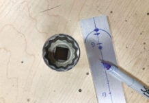
The first step is to obtain the precise layout dimensions from the instrument manufacturer (usually found in their installation guide) specified in inches or millimeters. Do not be stressed if you see measurements provided in decimal inches (for example 1.63 X 6.25 inches), as these can be easily converted to millimeters using an internet-based calculator. Using a millimeter ruler makes life easier when dealing with precise measurements. In the first picture, you see I have drawn the cutout with a marker and ruler. How precise does your drawing have to be? If you error on making the opening too small, you will have to file and file and file to make the instrument fit. Yuck. If you make the opening a little too large, this may not be a problem because the lip or trim of the instrument could cover an oversized hole. Take a look at your instrument to see how much wiggle room you have. You may be surprised!

Using a millimeter ruler makes drawing the cutout easier. This opening will fit a King transponder tray.
Next, we need to drill four holes (about 3/16 inch) at each corner of the layout, positioned so they fit completely in the corner without extending beyond the boundary lines. The purpose of these holes is to provide a positive stop to the saw blade so that we do not “overshoot the runway” as we cut toward the corners. Also, this provides stress relief for the aluminum at these corners, avoiding a sharp point. Four larger holes (note the arrows in the picture) should also be drilled halfway between the sides of the layout and positioned so they come in contact with the edge lines. They need to be large enough to allow insertion of the saw blade. These holes are where the saw cut will start—heading toward the corners.

A total of eight holes are drilled to aid in accurate cutting. Those with arrows provide convenient entry of the jigsaw blade for eight short cuts.
The next picture shows duct tape placed along each edge. This will protect the panel from the jigsaw and provide a straight edge to guide the blade. You can also cut from the backside if you redraw your opening on the back. I am using .063-inch thick aluminum stock for this panel. You might use something thinner or thicker as desired. The cutting can be performed with an inexpensive jigsaw that needs to be equipped with either a 24- or 32-TPI (teeth per inch) blade for cutting this sheet. The teeth are very small and close together, which makes for an easy, smooth cut. A total of eight short cuts, starting from the large center holes toward the corners and you are done! A file can clean up any irregularities in your cutting. But do not sweat the final appearance: that edge will never be seen again once your instrument is installed in its final home. Once you have confirmed the fit of the instrument into this first opening, you will have the confidence to make many more just like it.

Duct tape protects the panel while cutting and provides a cutting guide. These blades make cutting the sheet metal smooth and easy.

![]()
As the founder of HomebuiltHELP.com, Jon Croke has produced instructional videos for Experimental aircraft builders for over 10 years. He has built (and helped others build) over a dozen kit aircraft of all makes and models. Jon is a private pilot and currently owns and flies a Zenith Cruzer.


