 As we discussed in Part 1 last month, after buying and testing a new Sterba wood propeller for my Hatz biplane, it was clear it had too much pitch. For reasons discussed in the previous article, I had decided to replace the old Sensenich metal prop with a new wood prop. Selecting a propeller for an Experimental aircraft is always partly guesswork as no two homebuilts are exactly the same. To compound the problem, different prop makers shape and measure things differently, so the numbers aren’t directly comparable.
I had ordered a 74×47 wood propeller to replace the 74×50 metal prop. The increased blade thickness, and thus camber, in a wood prop means it will need less geometric pitch than a metal prop. I had (correctly, as it turned out) suspected that even 47-inch pitch might still be a bit too much, but it was a good starting point.
While a wood prop can be reshaped to reduce the pitch (within limits), it’s not so easy to increase it. Ed Sterba will rework any prop he makes to reduce the pitch for free, and after initial testing of the new prop I did send it back to him for a pitch reduction. The rework (to 46-inch pitch, not quite as much as I was looking for) improved climb performance somewhat, but testing showed it needed to be reduced still more to get the engine rpm where I wanted it and hopefully improve performance a bit more.
A reduction in either diameter or pitch will increase rpm. After considering the options—send it back again, trim the diameter a bit or rework the pitch myself—I settled on the third option. It’s not that difficult, but it does require careful and accurate work.
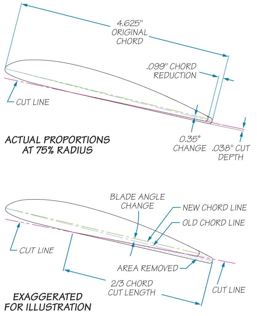
The pitch of a metal prop is adjusted by twisting the blades; no material is removed, and it can be increased or decreased. It’s not practical to increase the pitch of a wooden prop, but it can be decreased by removing a small amount of material from the lower (back) face, from mid chord back to the trailing edge, which makes the blade chord narrower at the same time. This moves the chord line up a bit in the back, lowering the angle of attack and thus the pitch. The resulting airfoil shape changes somewhat to a flatter camber, though maybe not enough to matter. All these things contribute to raising rpm by reducing the load on the engine. The leading edge and upper (front) surface are not altered. If one tried to increase the pitch of a wood prop by reworking the upper surface, the effect of the pitch increase would be counteracted by the chord reduction, so the change wouldn’t have much effect.
By the Numbers
I decided to shoot for a 1.5-inch pitch reduction to 44.5 inches, which should give an additional 75–150 rpm. The first step was determining exactly how much material needed to be removed. Not only is the actual amount very small, it varies along the blade due to the changing blade chord (width) and the radius. As described in the previous article, propeller pitch is defined as 2*π*R*tan(β). Working the other way, the blade angle β is given by:
β=arctan(pitch/2*π*R)
The material to remove at any given radius, then, is the tangent of the angle difference multiplied by the blade chord at that radius or:
material removed=tan(arctan(old_pitch/2*π*R)-arctan(new_pitch/2*π*R))*chord
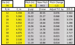
A spreadsheet made the calculations easy. For 1.5 inch of pitch reduction, the actual amount that had to be shaved off the trailing edge thickness varied from .014 inch at the tip to .076 inch at 12 inches from the hub. Inboard of 12 inches the airfoil is truncated by the hub faces, so I didn’t try to rework that area.
But how to do it accurately? Fourteen thousandths of an inch is a number more normally associated with precision metalworking than wood carving! One way to shape a wood surface is to make a series of saw cuts to the desired depth, then remove material between the cuts until the cuts disappear, not too different in principle from squaring lumber with a broadaxe between crosscuts when building a log cabin. Not wanting to take an axe to my propeller, however, a fine saw and an orbital finishing sander seemed a better choice.
Making the Change
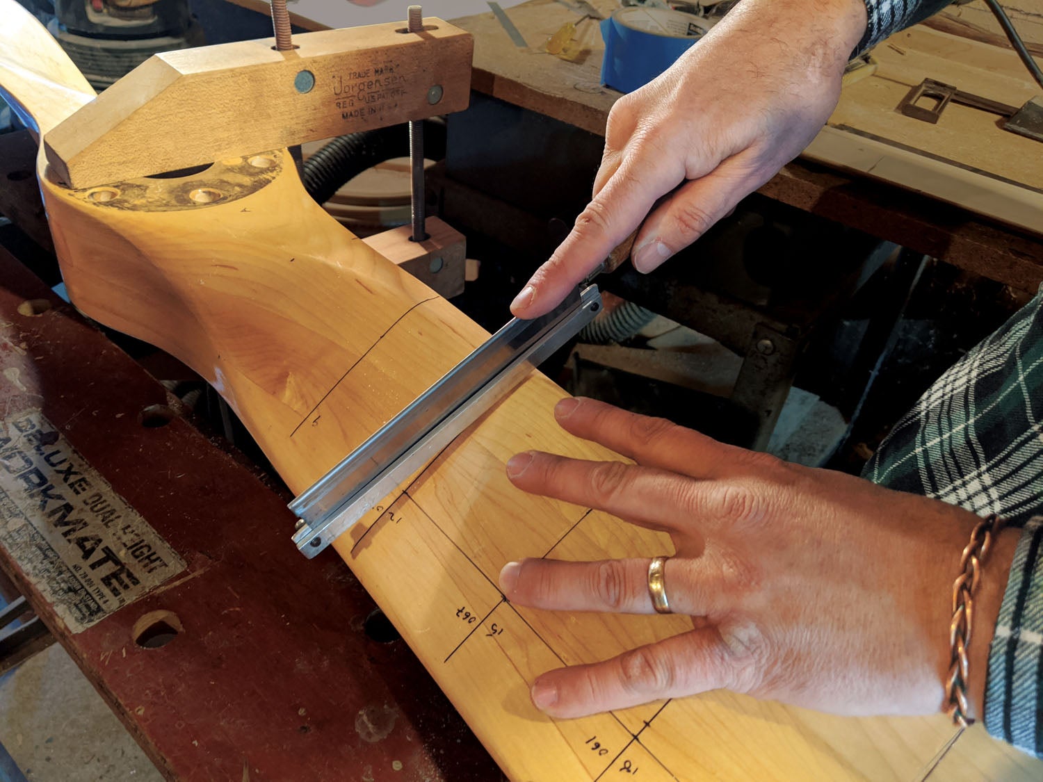
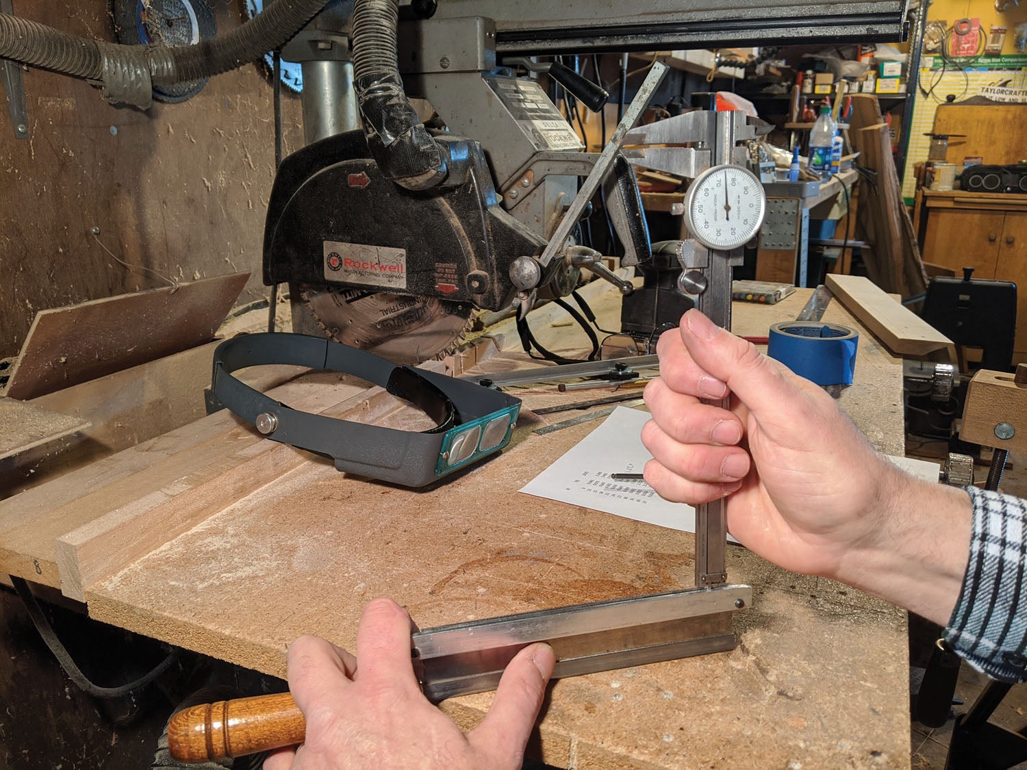
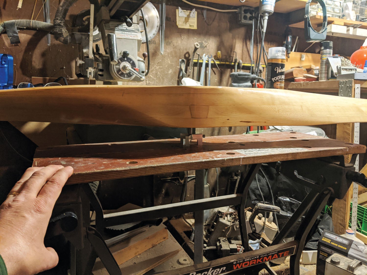
I experimented first on a scrap board with a Zona razor saw inherited from my father. By clamping aluminum strips to the sides of the saw so that only the required distance protruded, it was possible to make cuts of the proper depth and no deeper. I tried a few different ways to set the saw guide precisely using shim stock or adjusting screws, but simply tapping it into position with a tiny hammer and checking it with a dial caliper worked best.
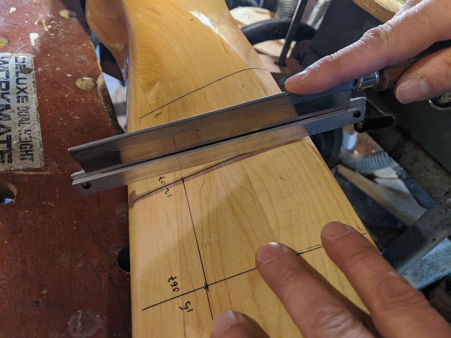
The cuts are full depth at the trailing edge, then the saw is carefully tipped forward to extend the cut forward until it fades out around two inches from the edge (I used 2/3 of the chord on the actual propeller). The orbital sander with 120-grit paper was then used to sand the face down until the cuts disappeared. This part is slow, as a finishing sander isn’t made for heavy material removal, but it makes it less likely to go too fast and remove too much material. The results on the scrap board were good enough that I was ready to try it on the real thing.
The first step was to draw chordwise lines at 3-inch increments, with a mark at the 1/3 chord point (i.e., 2/3 forward from the trailing edge) on each line, and lines connecting those points to give an approximate line to sand to. Next, the saw guide was set to the proper depth before making each cut.
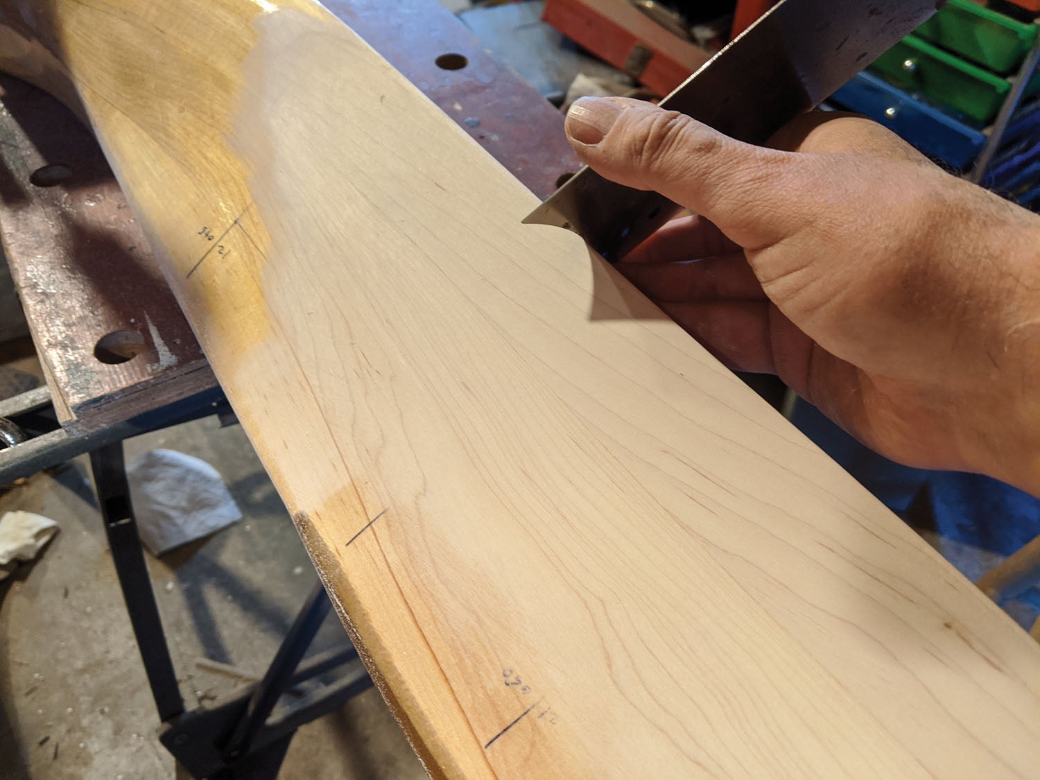
Taking a deep breath and dismissing the “Am I going to wreck a perfectly good propeller?” thoughts, I made the first cut, then the rest of the cuts, readjusting the guide for each pair. Then came sanding. The birch propeller is a bit harder than the soft pine test board, so it was even slower, but this is a place where it’s important to take your time. If you remove too much, you can’t put it back! Gradually the cut lines disappeared as the surface approached the desired new shape.
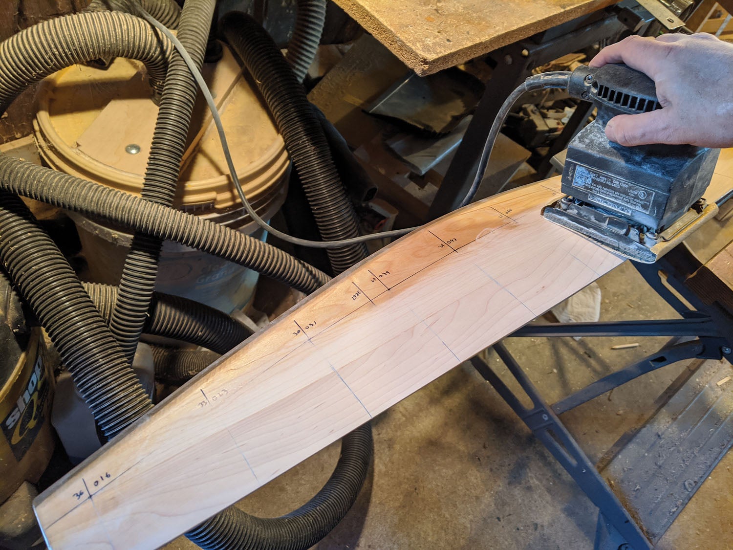
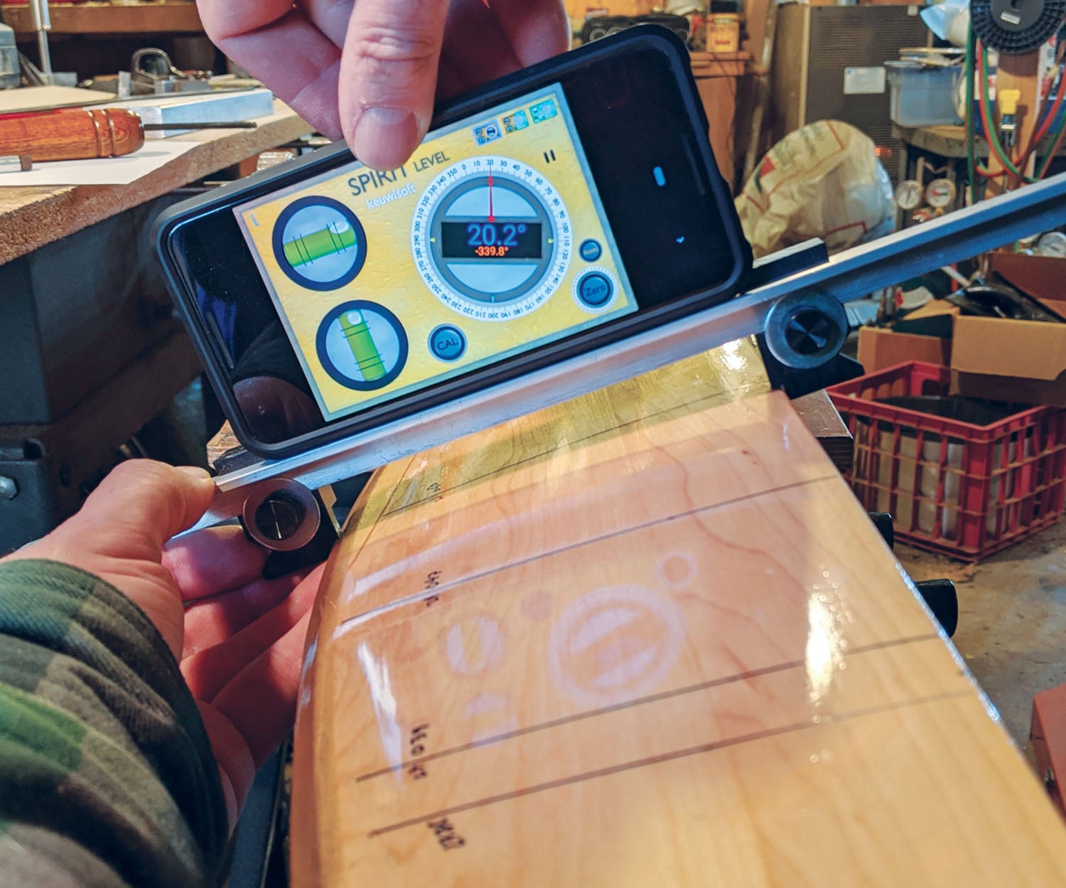
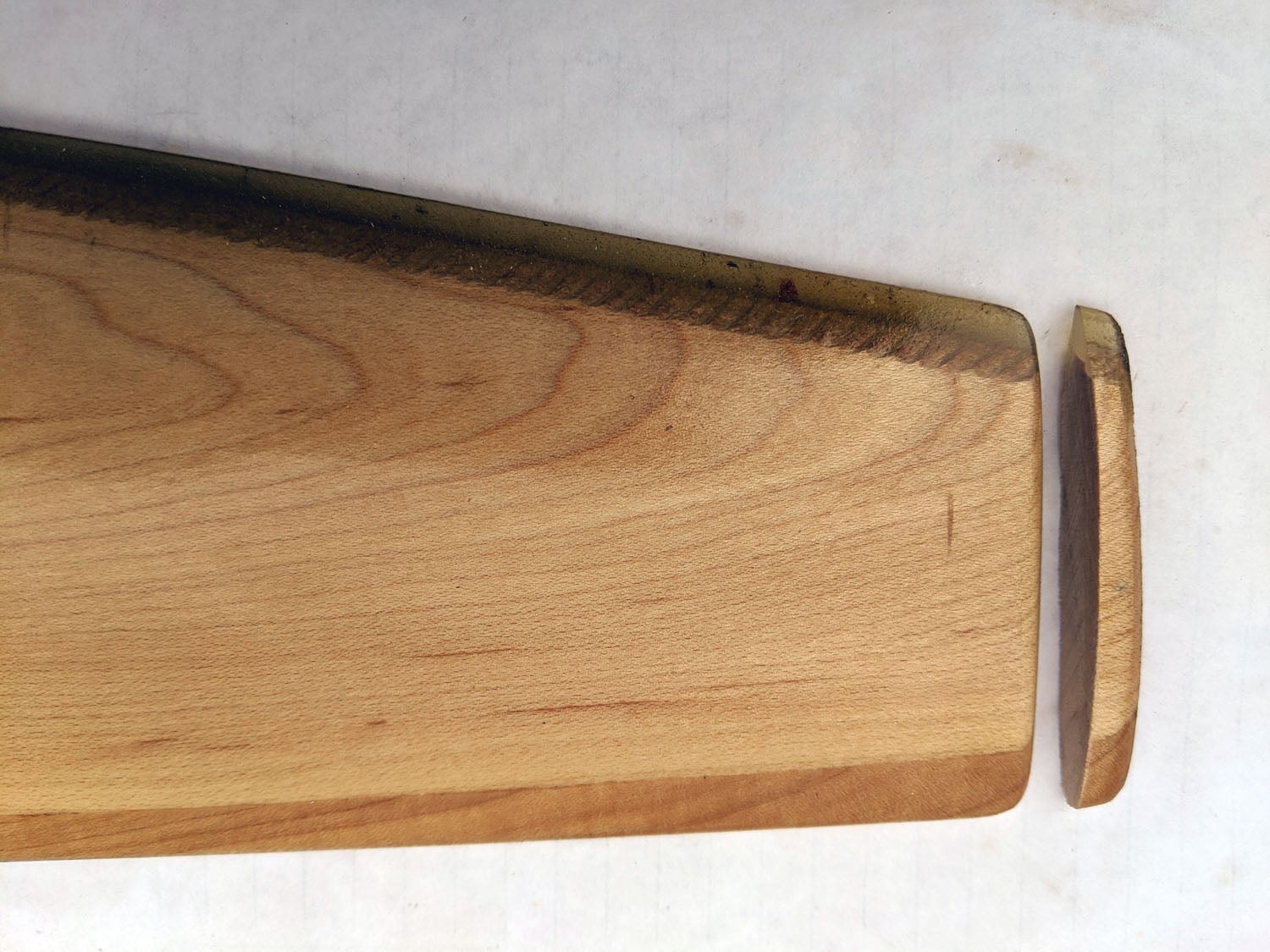
Once the surface was down to the desired contour, the material removed meant the trailing edge would now be too thin. Trimming it back to where it’s thick enough not to be fragile is what accounts for the chord reduction. A steel scraper took care of rounding it to approximately what it was before, about a 1/16-inch radius, with a bit more sanding to smooth it out. I must have removed the material evenly as the prop still balanced perfectly when I was done. New angle measurements, this time using a new homemade fixture and the Spirit Level Android app, showed a pitch of 44.3 inches, just about what I was shooting for.
After removing the remaining marker lines with denatured alcohol, it was ready for the first coat of rattle-can polyurethane varnish. I applied five coats over the next few evenings, then rechecked the balance. One side was a bit heavy at this point, so I shot another coat of varnish on the light side, which brought it into perfect balance and ready to mount.
Testing and One Final Adjustment
The following weekend brought good weather for testing. It was a noticeable improvement over the weather during previous test flights. Static rpm was up to 2500, which surprisingly was more than the metal prop, but in climb it was still 30 rpm less than the metal prop, with 75 fpm less climb. Full throttle in level flight was the same 2600 rpm as the metal prop and a few knots slower, but probably within the possible measurement error.
What next? At this point the prop was certainly “good enough,” but might it do better? Conventional wisdom says the metal prop will always be more efficient due to being able to be made thinner, but a few more rpm could increase performance—or decrease it. I didn’t think I wanted to reduce the pitch any further as it would be a lot of work for what would doubtless be a small (if any) gain, but perhaps a tiny bit off the diameter to increase rpm would improve performance? I decided to remove only 0.25 inch from each tip, reducing the diameter to 73.5 inches, just to see what would happen. If it showed any improvement, I could reduce it further. This was much easier than reducing the pitch; I scribed lines ¼ inch in from each tip, cut through the prop with the Zona saw and rounded the edges similar to the way it was before. Then after varnishing and again checking the balance, I went through the torquing and safety-wire ritual.
Trimming the tips gave me about 50 rpm more at my usual 60-knot climb speed. I repeated the sawtooth climb exercise out over the water again and checked cruise and top speeds on the way home. The rpm difference at full throttle in level flight was near zero, though the airspeed was down slightly, but no more than a knot or two. Cruise speed at 65% power was about the same. Back home, analyzing the GPS data showed the climb was the same or very slightly less, but as it was a warmer day with a lower barometric pressure (higher density altitude), that would be expected. Effectively no change, meaning there was no point to further trimming.
From here, all that remained was to finish the required five hours of testing and make the appropriate entry in the aircraft logbook. Earlier, while getting the test area approval from the FAA, I had asked about switching propellers back and forth. Could I terminate the test early if I removed the wood prop and put the original metal prop back on? No, they said. Since that’s another major change, the test period starts over. Seems silly to me since the original prop was already thoroughly tested but that’s the government for you, so the five hours had to restart from the last prop change.
So, I now have a 73.5×44.25-inch propeller, which is close to what most prop makers recommended. The performance isn’t quite as good as the original metal prop, but it’s a tradeoff like everything else in flying. If I was going to start this process again knowing what I know now, I think I’d start with a 76×43 or 42 or thereabouts and work from there. I’d love to borrow a long fine-pitch Borer prop from somebody’s Super Cub just to see what happens; I suspect the climb would be great, but the cruise speed would likely be slow even by biplane standards. Or maybe I’ll make one myself some day; it’s not that big a stretch from reshaping a propeller to making one from scratch. That would justify building a CNC router and buying a bigger band saw, but I don’t have room for either of those right now. And I have too many other projects anyway. Now that good weather is here, I think I’ll just enjoy flying my plane for now.


Dana. Great article!
One question: Airfoil aerodynamics studies have shown that a rounded trailing edge reduces the maximum lift (thrust) available. Wouldn’t a squared-off TE be better? or is there an issue with wood later chipping?
Ian H.
Any time you have a sharp corner there’s a chance for the wood to splinter. Like everything else, it’s a compromise.
I may be wrong; but I looked at the prop photo on pg 28 of the Oct issue and it appears as though the safety wiring on the studs at one o’clock and three o’clock are wired backwards. Unless those 2 studs are reversed threaded; they would be free to unwind a half turn or so before the wire resists that motion?!?!?!?! Yes …No Neil Nisita
Yup, you’re not the first to notice it. I did too, and corrected it before putting the spinner on. I only wish I’d checked the pictures as carefully as I did the plane, I’d forgotten that I’d taken a picture before noticing it, I was only looking for the clearest image.