You’d think that drilling two small holes in an aluminum casting shouldn’t take the better part of an afternoon. Yet…
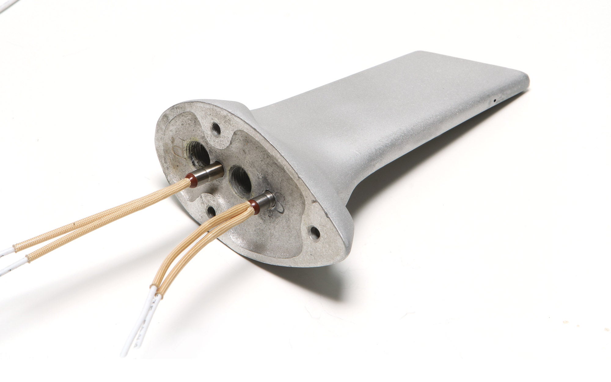
KITPLANES’ editor at large, Paul Dye, is a proponent of using Piper pitot masts in place of the L-shaped pitot tube typically installed on RV builds (see sidebar below). The Piper pitot mast comes in two basic flavors: heated (type 59041-XX) and unheated (type 65797-XX or 65797-XXX). The two parts are practically identical, at least on the outside. The obvious difference is the heated version has a pair of heating elements that sandwich the static port. Since a heated pitot tube is a requirement for IFR flying, heated is Paul’s preferred choice.
Paul’s latest project is an F1 Rocket. It’s not exactly an RV, but it’s kinda-sorta like an RV, so Paul planned on using a Piper pitot mast. However, finding a heated one for a good price turned out to be a challenge. In the process, Paul discovered that more than one RV builder had modified the more available and more affordable unheated pitot masts by DIY drilling the holes to add the heating elements. He also discovered that drilling those holes can be a bit tricky. One look at its tapered and quasi-airfoil shape and you realize you can’t just clamp it in a vise and start drilling.

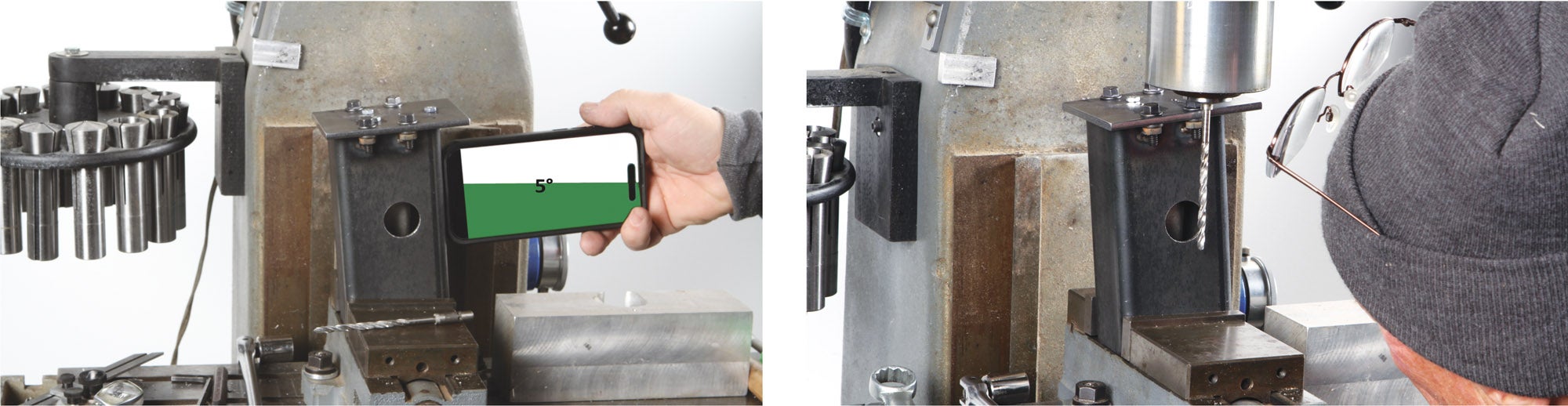
And it’s not just the shape that is the problem. At the 3-inch depth necessary to accommodate the CA464-356 (McFarlane part number) heater probes, there is barely 0.050 inch worth of material on either side. If you drill even the slightest bit off center, you’ll break out and ruin the part. As if that weren’t enough, the rearward hole has to be drilled at a 5° angle to maintain clearance between the static line and the back of the mast. If you make a mistake there, you could break out into the static line or the back side of the casting. In other words, there is little room for error.

I often talk about how making a fixture can often take more time than the task itself, and this is certainly an example! The time it took to drill the holes was but a few minutes. But getting to where those holes could be drilled…that took up the better part of an afternoon!
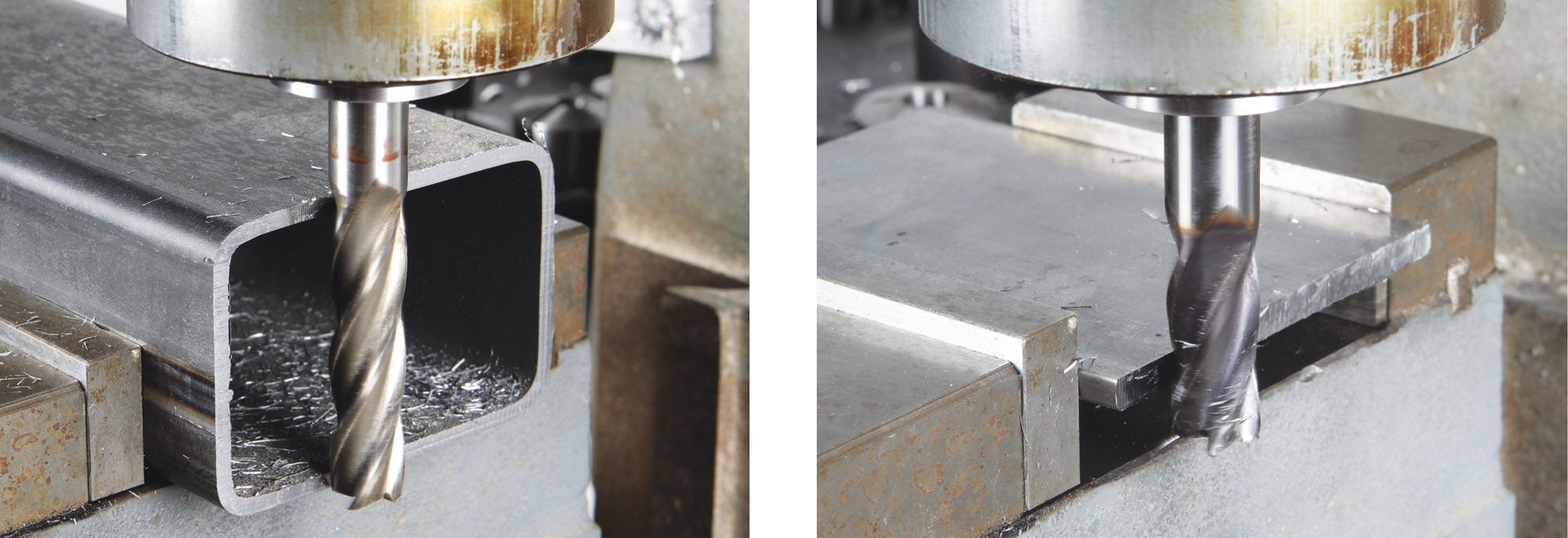
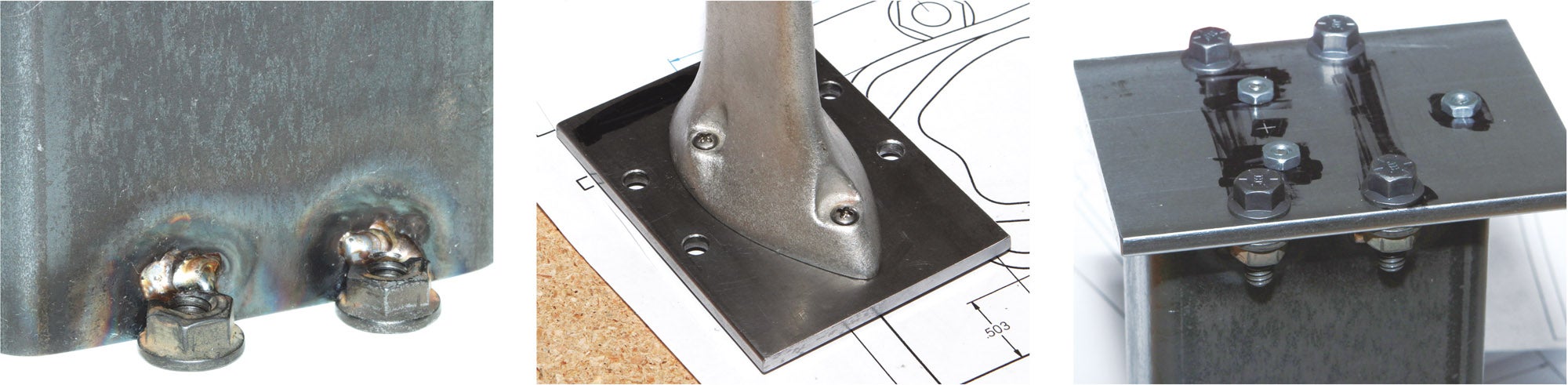
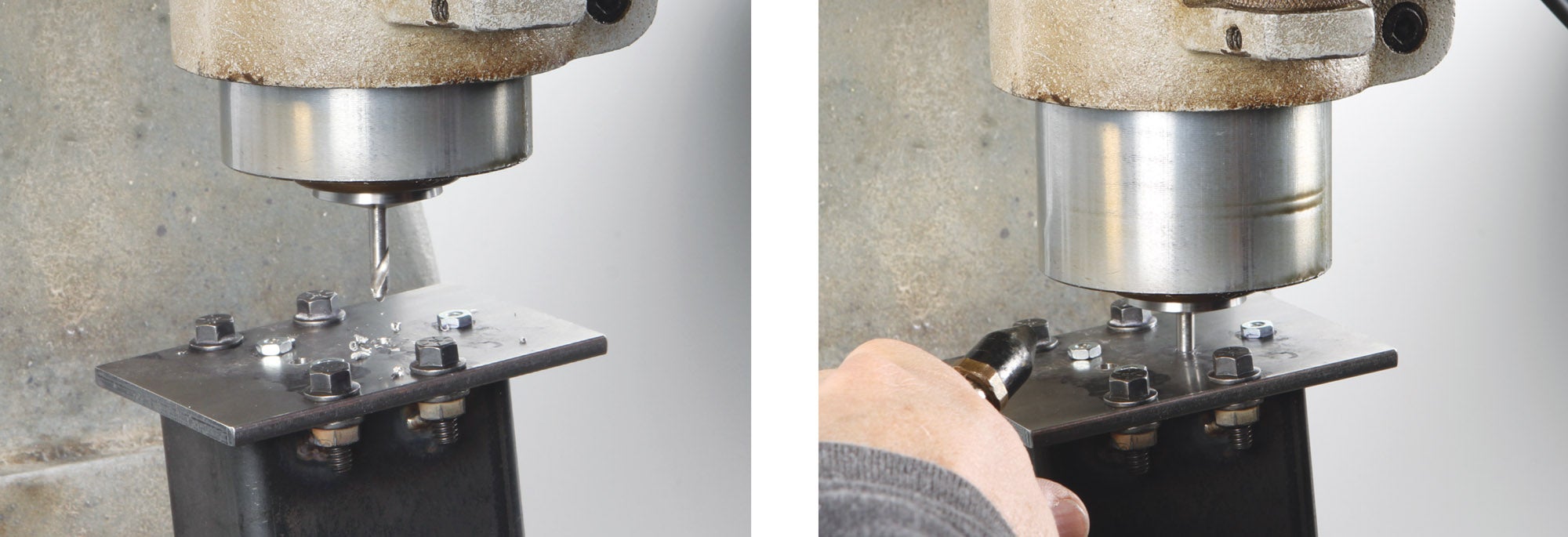
After a bit of discussion—and contemplation of what materials we had on hand—we developed a drill jig based on a length of 2×3-inch, 0.120-inch-thick rectangular steel tubing left over from the horizontal stabilizer jig Paul made for the F1 Rocket. This provided a “stage” to mount a top plate, which was designed to position the pitot mast on the centerline of the stage. With the top plate bolted securely to the stage, the mast was in perfect alignment for drilling.
I’m sure there are as many alternative ideas to do the same thing as there are readers of KITPLANES; this is just one way to do it. That’s it for now. Time to get back in the shop and make some chips!

 Wordless Workshop")


")

