Airplane design is inherently an iterative process. As we have already seen in our discussion of configuration layout, the airplane as finally built is virtually never identical to the first initial configuration.
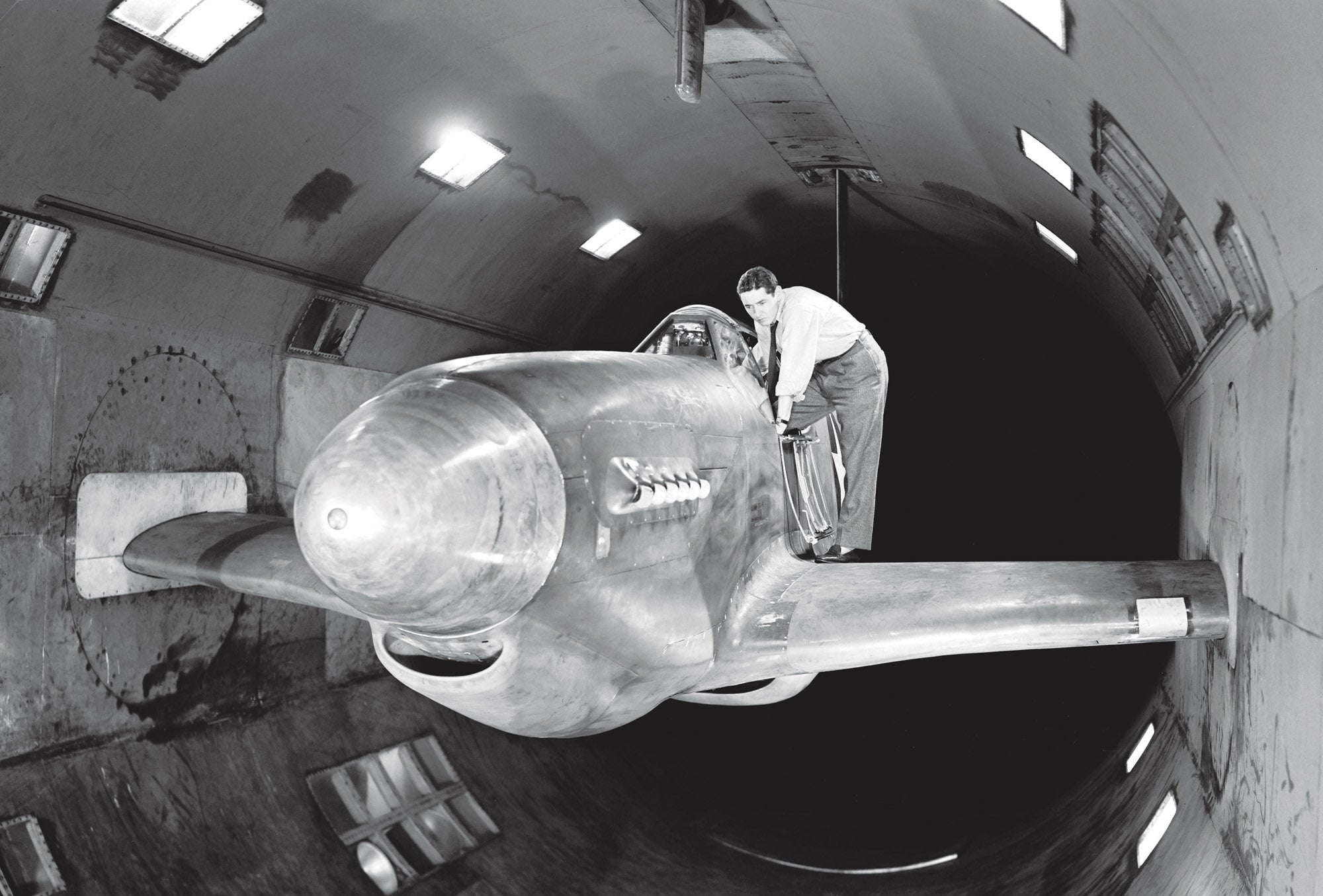
With the initial layout of the airplane complete, the design process moves on to a series of calculations and analyses to determine its weight, performance, stability and control. The level of sophistication of these analyses varies from project to project and may run the gamut from relatively simple, classical analyses to higher-order tools like full-configuration computational fluid dynamics (CFD). It’s also at this stage that sub-scale aerodynamic testing, either in a wind tunnel or using RC models, begins.
It’s likely that these tests and analyses will reveal some shortfalls or things that could be improved by adjusting the configuration of the airplane. The designer will use the results of the first round of analysis and testing to guide modifications to address these issues. It will usually take several iterations to converge on a fully workable design that meets all of the mission requirements.
Wind tunnel or flying model testing can confirm the aerodynamic characteristics of the airplane and reveal any aerodynamic issues. Typical wind tunnel tests evaluate multiple configuration details (for example tail shape and size) to explore options.
The airplane that finally gets built is almost never identical in configuration to the first drawing or the first wind tunnel model. Even after the aircraft is built and flying, some issues may be discovered in flight test that require fixes or modifications.
Common Areas of Change
The areas that demand the designer’s attention change as the design progresses. The first rounds of design iteration and modification should concentrate on things that will be difficult or impossible to change once the aircraft is built and flying. These include the primary structure of the airplane and the position and integration of the crew, payload and heavier systems.
Structure
The major structure and load paths must be fully defined before construction begins. It is very difficult to change the fundamental layout of the structure to fix problems that might appear late in the program.
Sizing
The first few design iterations are devoted to sizing the airplane properly and getting the required level of performance: speed, useful load, range, etc.
A common designer error is to assume the initial weight estimate is completely correct and size everything else on the airplane accordingly. The weight of the airplane is sensitive to many variables and it will typically take several design cycles for the size of the airplane to converge. Usually, the initial weight estimate will show that the wing size and possibly the power of the engine need to be adjusted. Since changing wing size changes weight and drag, and changing engine size changes engine weight and fuel burn, both of these will affect the weight of the airplane. After making these adjustments, the new weight can be calculated, and then the wing size and engine size reevaluated. If the overall design is viable, the weight change will get smaller every cycle. Hopefully, after a few cycles, the design will converge on a closed configuration.
The situation is a little different if the airplane must meet a not-to-exceed weight requirement. One example of this is the takeoff gross weight limit for U.S. LSAs. During each design iteration, the total weight is kept constant. The weight of the empty airplane is calculated and then the useful load is calculated. The design’s success hinges on getting the empty weight down to the point where the useful load is sufficient.
Sometimes, usually if the goal is to achieve either a very long range or endurance, the design will not converge. In this situation, the weight increase in every design cycle will be larger than in the previous cycle. This is a divergent situation, and there is no amount of resizing of the vehicle that will lead to a closed, viable design.
Wing Design
The wing must be properly sized to meet all of the requirements for takeoff and landing distance, stall speed and cruise performance. For most general aviation airplanes, overall wing size is driven be either stall speed or runway length. Once the proper wing size is settled, the details of the planform, aspect ratio and airfoil design can be tuned to get the best cruise performance. These details may change significantly in each design cycle, but once the wing design is frozen and construction begins, it is difficult and expensive to change.
Balance
Once the size has converged, the next priority is to get the airplane to balance. It’s rare that the initial layout will balance perfectly. The designer can move the forward and aft acceptable CG limits by changing the position of the wing and changing the tail size and/or tail arm. Both the position of the acceptable CG range and the acceptable CG travel between the forward and aft limits can be adjusted this way. It’s particularly important to iterate until the wing is properly placed on the fuselage because the wing structure and wing spar carry-through are one of the primary load paths on the airplane. The space needed for the carry-through structure affects where the crew and payload can be, so moving the wing can force movement of many other items. It is essentially impossible to change wing position once the airplane is under construction, so it’s vital to iterate this until the airplane balances properly.

Mass Distribution
The designer can move the physical CG of the airplane by moving internal components and payload fore and aft to bring the physical center of gravity and aerodynamically acceptable CG range of the airplane together to minimize the physical travel CG depending on how the airplane is loaded.
Design Flexibility
Wherever possible, it is a good idea to incorporate some flexibility into the design to help adjust its balance late in the game. On single-engine airplanes, two powerful variables the designer can use to move the physical CG are the length of the engine mount and the position of the battery.
Moving the battery from inside the engine compartment on the firewall to behind the cabin can move the CG aft quite a bit. On a prototype airplane, it’s wise to make sure there is a way to mount the battery in either a forward or aft position.
Moving the heavy engine forward or back can also move the CG significantly. The CG of the airplane can be adjusted by changing the length of the engine mount. It’s important to ensure the forward-fuselage structure can handle the loads that might arise, particularly if the engine moves forward.
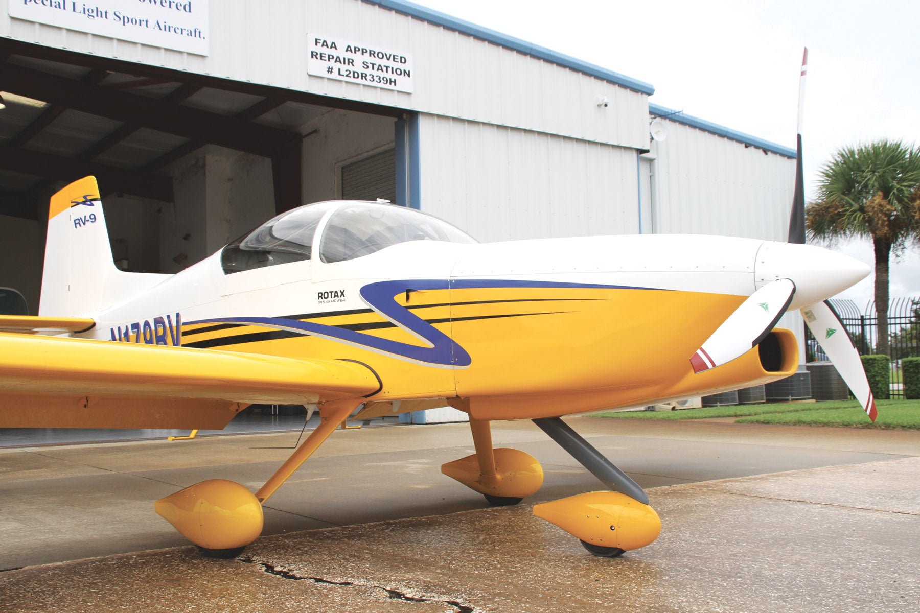
The engine often must move when an airplane is modified to use a different engine than the one it was initially designed with. The new engine will not weigh the same as the one it replaces. It may be heavier than the original or it may be lighter. One example is turbine conversions of airplanes that were initially powered by piston engines. The turbines are typically more powerful but significantly lighter than the piston engines they replace. Because of this, the turbine engine must be moved forward significantly to keep the empty CG in the same place. Turbine conversions will often have disproportionately long noses because of this.
This situation also illustrates a common phenomenon: One change often creates effects that require additional changes to compensate. On the long-nosed turbine conversion, moving the propeller forward and lengthening the nose can induce some directional instability that will require additional fin area to compensate for.
Once the airplane is built and enters flight test, there may be some characteristics that need to be improved. We will take a look at some of these in the next edition of Wind Tunnel.
Photos: Paul Dye and NASA via Wikimedia Commons.


