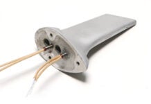
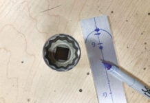
Spline shaft couplings are ubiquitous in machine and mechanism design. They exist in one form or another on virtually every vehicle on the road or in the air. While the engineering requirements for ANSI-standard involute splines can be a little complex and the tooling requirements specialized, straight-side and V-side splines (also called serrated splines) on shafts up to -inch diameter are easy projects for the home shop. All you need is a lathe, a vertical milling machine, and a 5C spin indexer.
The 5C spin indexer is the go-to tool for making splines. Every shop should have one. In previous columns I have used the spin indexer for a variety of cool jobs, such as knobs [“Home Shop Machinist,” September 2013] and flats [“Home Shop Machinist,” September 2016]. The indexer combines simple collet clamping with 360 whole number indexing. You could do the same job on a rotary table or dividing head, but the spin indexer is easier to set up and less complicated in operation. As long as you keep to a number that divides into 360 (e.g., 4, 5, 6, 8, 9, 10, 12, 15, 18, 20, 24, 30, 36, etc.) you can use a spin indexer.

The 5C spin indexer is conveniently clamped into position using the mill vise. For the straight-side spline, a slitting saw was used (shown); for the V-side spline, a standard end mill was used.
The straight-side spline example for this column was 3/8-inch diameter with nine splines. The grooves between each spline were cut 0.040 inch wide (the width of my 2-inch, 110-tooth slitting saw) and 0.020 inch deep. The V-sided spline example was 5/16-inch diameter with 18 splines. The V-grooves were machined with a standard four-flute, 3/8-inch diameter square-end end mill.
How many splines and what type (straight or V) depends mostly on what looks right for your project. For the projects shown, I used the 2D drafting module in Solid Edge (available from Siemens for free.) to make a number of sketches before deciding the spline count. Any basic drawing program or CAD software can be used. You can also use a pencil and a protractor, but CAD is preferred because it will give you the most precise dimensions to reference your tool position and machine setup.

The width of the grooves for the straight-side spline was based on the 0.040-inch-wide slitting saw. After sketching various options, I decided that nine splines machined to a depth (D) of 0.020 looked the best.
A spline shaft is not much use unless you have a handle, knob, or coupling, for it to mate with. To assure compatibility with your custom spline, prepare the shaft stock and the broaching stock at the same time.

Touching off the tool from the 12-o’clock and 9-o’clock positions simplifies the set-up. A nine-spline example is shown for clarity, but the idea is the same for any practical number of splines.
The broaching tool starts out as a length of W1 (W for “water hardening”) tool steel the same diameter as your spline shaft.
W1 rounds are also called “water hardening drill rod.” W1 is precision ground and available in common drill sizes from 0.062 to 2-inches diameter. The cost for a three-foot length of 0.3125 (5/16) was $5.20. The three-foot length of 0.375 (3/8) was $8 (prices from McMaster-Carr). Depending on your project, you might consider using W1 (in the unhardened state) for the spline shaft as well.
W1 tool steel is ideal for making home-shop broaches because it is very forgiving to machine, heat treats easily with a propane torch, quenches in water, and can be tempered in a toaster oven. The resulting tool will have good hardness (50+ Rockwell C) and can be used to broach more than a handful of sockets before any appreciable wear.

For a 5/16-inch shaft (left) that will have 18 splines, the Y and Z tool edge position dimension “D” = 0.067 inch. This orients the first groove to be cut on the 45 position, and after indexing (clockwise in this view) all subsequent cuts are on that same 45 position (center). Note the root diameter (right), which determines the pilot hole necessary to make the broach and, subsequently, the female socket.
Other than the tool position (for straight-side splines the tool is on the shaft centerline at 90 and for V-sided splines it’s at 45), the procedure for milling the grooves is the same.
Put the shaft in the indexer with one to two inches of length protruding. Since you can’t mill grooves right up to the collet (the tool will hit [crash into] the collet), you need to account for the tool diameter and figure out how much stock needs to protrude to get the desired groove length. Keep in mind you want the stock to protrude as little as possible and still be able to mill the grooves to the desired length. Once you’re satisfied, set and secure the X-axis table stop (see “Home Shop Machinist,” July 2017). This will assure the grooves are all the same length.

Turn a length of W1 tool steel to resemble the above form. Note the step in diameter and 5 relief angle behind the leading edges of the first two steps. The pilot hole diameter is dictated by the ID of the root of the spline grooves. Leave at least two inches of extra length (100% of OD) for holding in the collet and to allow tool clerance from the indexer when milling. After grooving, lathe-turn a relief to the pilot hole diameter and part off.
Tighten the collet and set the indexer to “0.” You are now ready to touch off the tool and dial in the cutter position (shown in the sketches as “D”). Use an edge finder to locate the side of the shaft and set zero. To zero the top edge, with the mill off, center the cutter over the shaft and bring the quill down (or crank the table up) until the cutter is almost, but not quite, touching the stock. Take a piece of regular inkjet/laser printer paper and measure the thickness. It should be about 0.004 inch. With the paper between the cutter and the stock (and the mill off), slowly bring the table up until you just begin to feel the cutter starting to drag on the paper. Stop there. Set the Z axis dial to zero + 0.004 (four thousandths). This method prevents the tool edge from chipping or gouging the part and, with practice, can be as accurate and reliable as any other.
Position the cutter clear of the free end of the part and dial the table in to line up the cutter to make the first groove. For the V-grooves I ran the 3/8-inch end mill at 900 rpm and for the slitting saw, 450 rpm. Keep the feed rate slow and easy to the stop limiter, and then back completely out of the cut at the same slow and easy rate. Once clear, pull the indexer lock pin and rotate the part according to the number of splines you want (e.g., 20 for 18 splines and 40 for nine splines). Repeat until all splines have been milled.

CAP(Left) Making the first groove for the straight-side, nine-spline shaft. (Right) The broaching blank after all the grooves have been milled. Note how the mill’s travel limiter assured all the grooves are identical length.TION
That’s all there is too it! We’ll pick up next month with heat treating the broach and making the sockets for the handle.

![]()
Bob Hadley is the R&D manager for a California-based consumer products company. He holds a Sport Pilot certificate and a Light-Sport Repairman certificate with inspection authorization for his Jabiru J250-SP.


