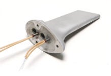
An assortment of lathe-turned spheres made using the OMW tool. Left to right: Delrin half-spheres for a set of control levers, a threaded Delrin knob, a split maple hardwood knob, and a solid aluminum ball end.
The project’s done, phase one is complete, and now you’re flying to your heart’s content. After so many years building, you’re finished. Done! Now what? You don’t want to start another project, but you need to deal with builder’s withdrawal. What you need is a day project (as in done in one day). If you are a regular reader of this column, you know what I’m talking about: knurls, doo-dads, and titanium washers, to name a few. (Past articles are available to subscribers.) This month is another fun day project: spherical (ball) knobs.
At first glance, turning a perfect sphere on a machine (the lathe) with only linear tool movement looks improbable, if not impossible. Yet, with an accessory called a sphere and radius (or ball and radius) tool, it can be as easy as one-two-three.
Sphere (and radius) making tools come in a variety of configurations. Before CNC machines, ball and radius attachments were standard accessories for tool room lathes. The Hardinge example, in particular, combines the highest level of precision with stout robustness. Although they haven’t been available for years (Hardinge no longer makes manual lathes), these “obsolete” tools command top dollar on eBay.
The OMW radius tool (left) and two examples of shop-made ball and radius tools (right). (Tools on loan from Schwien Engineering and Copp Industrial Manufacturing.)
Sphere-making tools for the home shop cost between a hundred and two hundred dollars. The cost factor equates to a light-duty tool that, while completely functional, is designed for occasional use and leaves precision up to the skill and persistence of the operator. For the examples in this column, I used a “large-diameter” OMW Radius/Ball Turning Tool. This can be purchased from LittleMachineShop.com for $140.00 plus shipping.
Another option is to make your own. There are dozens of how-to projects for sphere and radius tools online. Most are the basic C-frame style, but some are more complex and feature precision that rivals, or in some cases exceeds, commercial tools.
The basic function is the same regardless of the design or origin (commercial or homemade) of the tool. A base or frame that has a pivoting segment with a handle is clamped to the lathe and the cutter height set to the lathe centerline. The workpiece is positioned in the lathe and the pivoting segment checked for clearance. The pivot is adjusted to the center of the sphere workpiece, and the dials set to zero. Back out the cross slide or carriage, start the lathe, and start to nibble away. Eventually you creep your way back to zero and have a sphere! The actual movement of the cutter is controlled by a handle that is connected to the pivoting segment. It’s a little weird, after using handles and dials, to move a cutter by direct hand control. But you immediately appreciate the direct feedback from the tool: take too heavy a cut and you feel the increased tool resistance.
The instructions that came with the OMW tool were excellent. They provide every detail necessary to set up the tool and achieve good results from the start. Of course you’re not limited to spheres per se. You can create any radius you want (within the limits of the tool), convex or concave.
Making spheres requires some basic planning. How the sphere will be fixed to the end assembly determines the work holding strategy. If it’s a knob for push-pull control, it will screw onto a threaded rod. If it’s a handle for a quadrant, you might turn it from two halves clamped together. The examples I made illustrate the basic process: Sketch out an idea, prep the stock, set up the tool, and make chips!
Example 1: Maple Hardwood Split Ball
The split ball is fixed with a countersunk socket head screw (left). The turning stub is basically a length of bar stock machined on one end to replicate the -inch x -inch lever that the sphere will be attached to (right).
Make two identical blanks with slots for the turning stub (left). Drill a clearance hole through one side. Drill and tap the other for a coarse-thread screw. Maple, a tight-grain hardwood, can be coarse-threaded with regular taps (right).
Counterbore the clearance hole to the appropriate depth (left). Bolt and tighten the halves together, mount on the lathe, and rough turn to a cylinder (right).
Setting the tool position to the correct radius with a planer gauge (left). Center the OMW tool according to the instructions (right).
Using light cuts and very slow tool movements, start nibbling away at the corners. Eventually the sphere starts to emerge (left). For wood knobs, as you creep toward the final dimension, cut “downhill” on the grain. In other words out from the larger diameter to the smaller diameter (red arrow). This will reduce the tendency of the wood to tear (right).
Lightly sand with 180-grit sandpaper to remove the tool marks. Finish with a light touch of 220, 320, and then 400 grit.
Example 2: Delrin Thread-On Knob
A 2D sketch (left) provides the basic detail for the depth of the threaded hole and the stem extension for chucking in the lathe (right).
As before, nibble away at the corners until the sphere starts to develop, then take a final, sweeping light cut (left). Because of the close proximity of the chuck to the tool (the mounting stub should have been a little longer), I had to change tools to shave the shoulder down. Note the fresh tool marks (right).
A light touch with 180, 200, 320, and 400 sandpaper is necessary to remove the tool marks. The cutter on the OMW tool comes to a sharp point so even the slowest feed rate and lightest passes still generate surface marks (left). The business end of the knob ready to be installed (right).
Example 3: Delrin Half-Spheres for Control Levers
Procedurally, you turn them the same way except one half at a time bolted to the stub. The material is Delrin (a free-machining plastic). Unlike the maple wood example, Delrin has no grain structure and machines the same in either direction.


