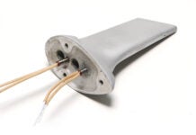
The cases of the Jabiru 3300 engine are bolted together and then fly-cut to create a book-matched look.
Did you ever wonder what kind of tool makes those graceful machine marks on factory-made brackets and manifolds? Or the incomparably machined cases of Jabiru engines? It’s the result of surface-planing the part (or parts) with a tool called a fly cutter.
Fly cutters are most often used for surface planing, which is the subject of this article, but they can be adapted to do a variety of jobs. For example, they can be used to cut teeth in gears or sprockets, and, by taking advantage of the tilt function of the milling machine and by varying the tool extension, to make a variety of decorative scallops.
The most common type of fly cutter for the home shop is the single-point variety. These have a cylindrical body with a slot for a square cutter. The cutter is angled 20 to 30 degrees for clearance. Single-point fly cutters are easy to set up, and deliver excellent results, even with a small mini mill or low-powered bench mill. Multi-point cutters, also called face mills, are the workhorse of professional machine shops for large surface milling (which is the same as fly cutting). But cost, power, and machine rigidity requirements go up exponentially as you increase the number of cutters and cutting diameter.
The smallest fly cutter in this photo (foreground) has a -inch shank with a -inch- diameter head. The largest has a -inch shank with a 2-inch-diameter head.
Compared to most forms of mill tooling, single-point fly cutters are relatively inexpensive. Due to the basic low-tech nature of the tool, they are often sold in sets of three (small, medium and large) with bits, for less than $100. The two sets shown in the photo are typical. The small -inch shank set is for the mini mill in my home shop. The larger -inch shank set is for larger machines, such as a Bridgeport or similar style knee mill.
Fly cutters are pretty basic: A cutter is fixed into a slot in the head with setscrews. Shown are two size extremes: a 2-inch-diameter fly cutter with a 5/16-inch square bit and a -inch-diameter fly cutter with a 3/16-inch square bit.
Getting good results with a fly cutter requires that the cutter geometry be correct for the material you’re working with and, if you’re surface planing, the mill head must be properly trammed (set square to the table) to assure the cutter is square to the mill table.
Fly cutting is primarily for final dimensioning or finishing, and not for making heavy roughing cuts. Often fly cutting is done with the tool overhanging one or more edges of the part. This is called an interrupted cut. Fly cutting tools and holders are designed for light-duty interrupted cutting. Attempting to whack away huge chunks of material can stress the tool, the holder, the machine and even the part. What’s a light cut? It depends on the machine and the size cutter. A 0.050-inch pass on a 5-hp Bridgeport knee mill would be a light cut. On a mini mill or benchtop machine, 0.005 to 0.020 might be the limit.
The high-speed steel (HSS) tool bits that come with fly cutters typically need to be both shaped and sharpened before use. All it takes is a few minutes at the grinder to fix an edge on the tool. For planing with a fly cutter, you can use the same basic angles that apply to single-point HSS lathe tools. I planed aluminum for the examples in this article, so that is what is depicted in the diagrams.
This diagram shows the basic face (10), end (9), and flank relief (5) angles. For additional information on grind angles visit www.steves-workshop.co.uk/tips/toolgrinding/toolgrinding.htm.
How far you can extend the tool depends on the holder diameter and bit length. The farther out you extend the tool, the more likely you will get chatter. It’s also possible to set the tool out so far that it creates a noticeable out-of-balance vibration, especially on smaller machines. Vibration is bad, not just for cutting quality, but also for the machine.
The spindle rpm and feed rate depend on the material. Using a 2-inch diameter fly-cutter as an example: For steel and cast iron, start with a spindle rpm of 150-200. Set the depth-of-cut to just scrape the surface, and do a test cut. Vary the feed rate as you turn the handle and evaluate the cut as you go. The target removal rate for fly cutting steel is 80-100 surface-feet-per-minute. Don’t worry about getting that exact number! Just know that its achieved by a relatively slow spindle rpm and relatively slow X-axis (left to right) feed. For aluminum, set the spindle rpm to 800-1000 (target removal rate is 500-600 surface feet per minute) and do the same test: Set the depth-of-cut to just scrape the surface and do a test cut. Vary the feed rate as you turn the handle and evaluate the cut as you go. It may take a few passes to get a feel for what produces the smoothest surface.
The cross-hatching tool marks (red lines) indicate the mill is square and the machined surface is flat.
Issues that might come up when fly cutting are out-of-square or tool chatter. One telltale sign that your mill is trammed square (or not) is the presence of crosshatching in the tool marks. If you do not get crosshatch marks, the fly cutting action is creating a scalloped surface. Unless that is what you want, the mill head needs to be square! There are a variety of online resources on how to tram a mill using dial test indicators. Since my mini mill tilts only left or right, I tram it with a precision machinist’s square. Use a machinist’s square-a carpenter’s square is not precision!
Moiré patterns sometimes appear. They are a sign that something is wrong. This example resulted from the tool being less than perfectly sharp, causing chatter.
Using a small fly cutter on the mini mill. This width of the piece is 2 inches wide. The fly cutter is set to a 2-inch-wide cut for 1/8-inch overhang per side. The depth of cut is 0.010 inches and the rpm is 1000. The finish is about as close to “glass smooth” as you can get with a machine tool.
Tool chatter or a rough finish could be the result of one issue, or a combination of issues. If you are taking a very light pass (0.010 inch or less) and getting chatter, double-check that the bit is correctly sharpened and that the cutting angles are correct for the material. A dull tool can also cause chatter and weird-looking moiré patterns (see photo). In this case the tool extension was very short, but the dullness of the cutter caused a less-than-clean cut, which induced a vibration. The surface after this cut felt “fuzzy” and rough, instead of smooth and soft.
If the tool is sharp, the next step is to reduce the amount the bit is extended from the holder. While this reduction in cutting diameter might mean you can’t surface the whole width of the part in one pass, it’s better than getting chatter! If you love the “one pass” look of fly cutting, but your holders are not rigid enough, you can make your own oversize tool. That’s one of the great benefits of the home shop-if we don’t have the right tool, we can sometimes make it!


