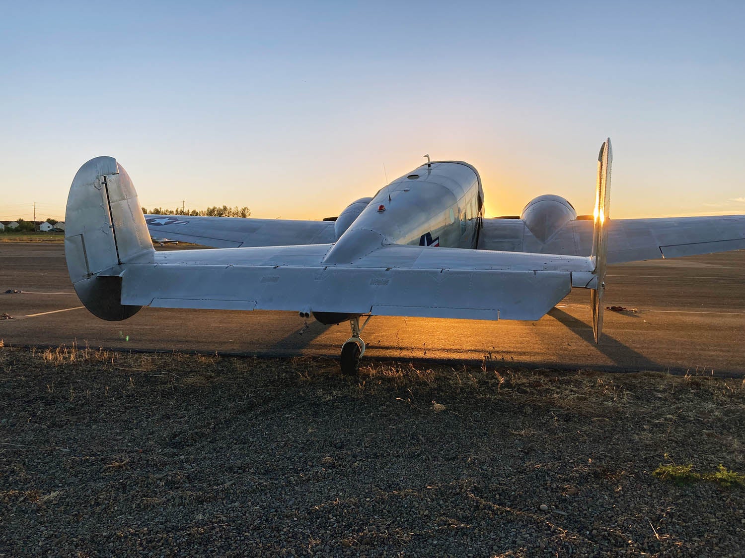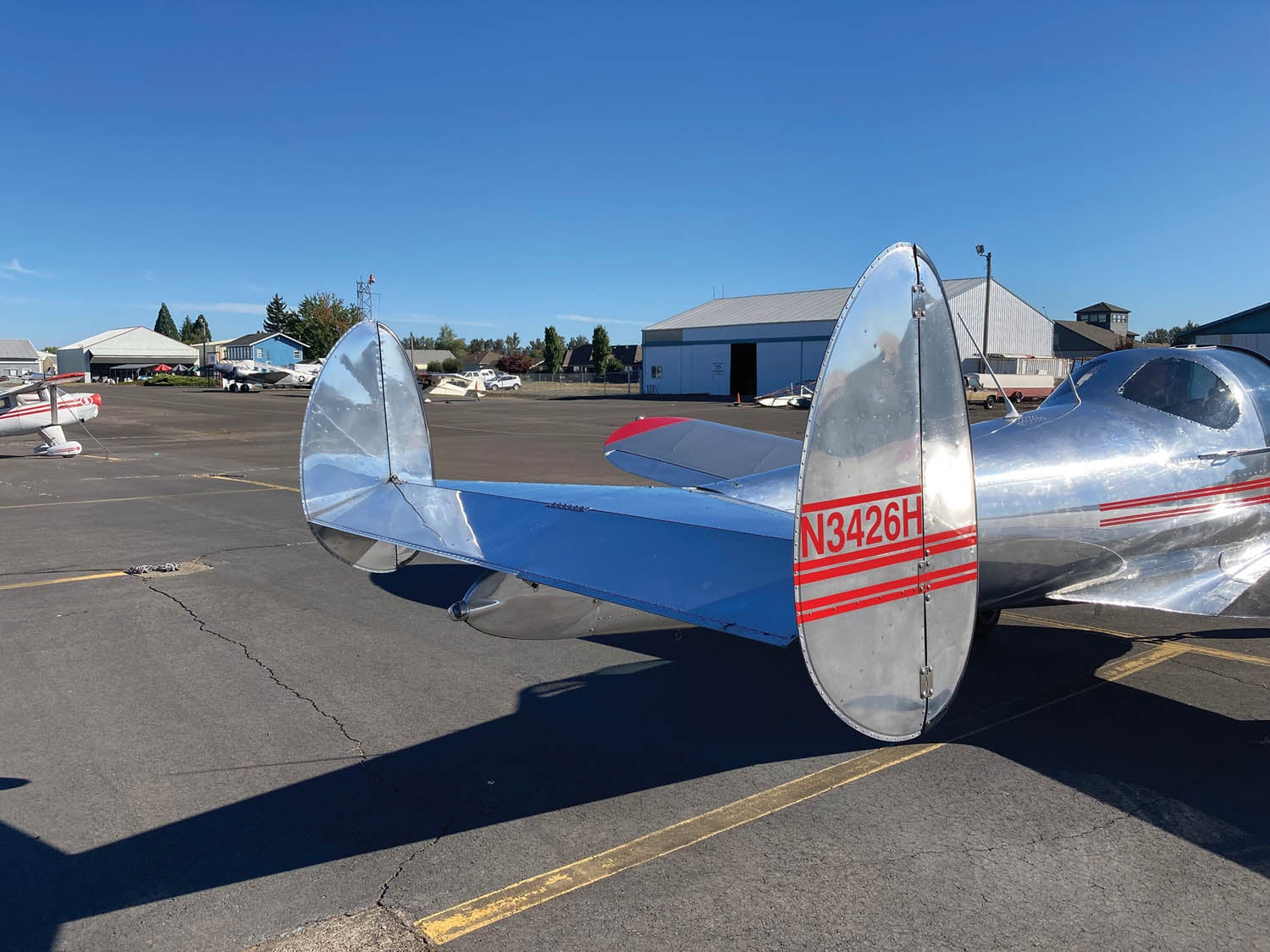
The majority of airplanes use the conventional tail configuration with a single, centrally mounted vertical tail and rudder. Sometimes, however, the vertical tail is separated into two or more surfaces.
One such configuration has vertical fins mounted to the tips of the horizontal tail. These fins can be the only vertical tails on the airplane or can be used in combination with a center vertical.
Directional Stability Improvement
Tip fins on the horizontal tail are sometimes added to an airplane with a single vertical tail to increase directional stability. Often this is a result of a modification to the airplane that makes the original vertical fin inadequate to properly stabilize the airplane. Tip fins are common features of floatplanes. The floats themselves are directionally destabilizing, so adding floats may make an increase in fin area necessary to maintain good flying qualities. One way to add the needed extra fin is by putting tip fins on the horizontal tail.
Hangar Height
On an airplane with multiple vertical fins, each fin is smaller than the single fin the airplane would otherwise need. Splitting the fin into two or three parts reduces the overall height of the tops of the fins and hence the overall height of the airplane.
Over time, as airplanes got bigger the height of their fins increased accordingly. At the same time, in the WW-II era, tricycle landing gear began to replace tail-dragging gear for larger airplanes. This moved the tail of the airplane up when at rest and further increased the overall height of the plane at rest. The result was that a configuration with a single vertical tail would not fit into existing hangars. Designers incorporated multiple fins on such airplanes as the B-24, B-25 and Lockheed Constellation to keep the tip of the fins low enough to fit into the hangars available at the time.
Structural Considerations
A multi-fin tail has both structural advantages and disadvantages. The overall weight of the tail system (horizontal + vertical) will be a function of the relative importance of these for the specific configuration.
On the positive side, each tail is smaller, so the bending moment on the fin spars is less. This advantage is increased with a full H-tail where the fins are mounted to the horizontal tail near the vertical centroid of the fin so that the length of cantilever for the fin spar is only half of what it would be for a similar fin mounted at its root.
An additional structural advantage is that the centroid of the fin area is much lower, so the aerodynamic side force generated by the fin produces lower torsional loads on the fuselage than a single central fin cantilevered upward from the top of the fuselage would.
The primary structural disadvantage is that the horizontal tail must have additional structure to attach the tip fins and also additional structure to carry the aerodynamic loads on the fins.
Aerodynamic Effects
Pitch
The fins mounted on the tips of the horizontal tail act as end plates. They increase the lift-curve slope of the horizontal tail, which increases both the stabilizing effect of the horizontal tail and the control power of the elevators. This effect may allow the horizontal tail to be smaller for the same level of stabilizing effect.
Directional Stability
The fins of a multi-fin tail are typically lower aspect ratio than the single vertical tail that they substitute for. The fins at the tips of the horizontal tail also are not end-plated by the fuselage like a single centrally mounted fin is. Both of these effects reduce the lift-curve slope of the fins. This means that for a given total fin area, the fins of the multi-fin tail produce less directional stabilization than a single higher-aspect-ratio fin. Accordingly, the total fin area needed for the multi-fin tail will be larger than for a single vertical configuration.
Wake Effects
For aircraft with bluff bodies that shed turbulent wakes, a central vertical fin may be immersed in the wake of the upstream components and be unable to stabilize the airplane. Mounting the vertical fins at the tips of the horizontal tail moves the fins out of the aerodynamic wake and places them into clean airflow where they can function effectively to stabilize the airplane.
This situation is common on pusher aircraft, which tend to have bluff afterbodies upstream of the tail. On gyroplanes, for example, it’s common to have a three-fin configuration. The central fin has the rudder and is immersed in the propeller slipstream so the rudder is effective. The tip-mounted verticals on the horizontal tail provide most of the directional stabilization.
Gyroplanes also tend toward multi-fin configurations for geometric reasons. The acceptable height of the vertical fin (s) is limited because the fins are below the rotor and the fins must be short enough so that when the rotor blades flap as they spin they remain clear of the fins.
Spin Characteristics
The H-tail configuration with the fins mounted on the horizontal tail generally has good spin recovery characteristics. The portion of the fins below the horizontal tail remain in clean air at high angles of attack and retain their effectiveness. Also, the advancing fin in a spin is moving into clean air as the airplane rotates and provides effective anti-spin yaw damping.
Slipstream Effects
Moving the vertical fins off of the centerline of the airplane changes the way the fins interact with the propeller slipstream. This can be used to either move the fins out of the prop wash or deliberately immerse them in it, depending on the configuration of the airplane and the designer’s intent.
On a single-engine tractor airplane, the swirl in the slipstream caused by propeller rotation is a primary cause of P-factor on an airplane with a conventional tail. Because the vertical fin is above the fuselage but not below, the fin sees some sidewash from the swirl in the slipstream. This generates side force on the fin, causing a yawing moment that the pilot must compensate for with rudder. This effect is most pronounced at the high power settings and low airspeeds typical of climb.
Mounting the fins on the tips of the horizontal tail takes them out of the propeller slipstream and eliminates this effect. This is why the Ercoupe has an H-tail configuration. Eliminating most of the P-factor was key to making the airplane compatible with two-control operation.
On a multi-engine airplane, using an H-tail deliberately places the fins and rudders in the slipstream of the propellers, which can increase the rudders’ control power. In an engine-out situation, having a rudder in the slipstream of the operating engine increases the rudder power available to offset the yawing moment caused by the loss of thrust and drag of the failed engine.

Mechanical Considerations
The control linkages for a tail with the fins and rudders mounted outboard on the horizontal tail are more complex than for a single vertical fin/rudder configuration because the controls must be routed outboard through the horizontal tail to the rudders.
Care must also be taken in the layout of the elevators and rudder to ensure that the rudders do not clash with the elevators when a rudder deflects inboard. There are several ways to accomplish this. The rudder hinge line can be aft of the elevator trailing edge, or the tips of the elevators can be cut away at an angle to clear the deflected rudders. Another approach is to arrange the rudders so they deflect outboard only. This works well mechanically but sacrifices some rudder control power.
A three-fin configuration with fixed outboard fins and the rudder on the central fin eliminates these issues and can work well, provided the single central rudder has enough control power. This arrangement of a central (often all-moving) rudder in the prop wash combined with outboard fixed fins to augment directional stability is a common feature of modern gyroplanes.


