Ever look at a part and wonder, “How did they make that?” I do that all the time. When the solution isn’t particularly obvious, it becomes a thought exercise, as in, “How would I make that?”
This month’s project started out as one of those thought exercises. The project was suggested by Aaron from Michigan, who was looking for a light-duty 1⅞-inch socket for tightening large axle nuts to a very low, but precisely calibrated, torque specification:
“My company requires all wheel hub nuts to be torqued with a socket [not a crowfoot wrench]. This is an issue with military birds as well. The size of the axle nut requires you to use a ¾-inch drive socket with adapters to get down to the inch-pound torque wrench, which has a ⅜-inch drive. The socket and adapters are heavy and stupid. Having a 1⅞-inch socket with a ⅜-inch drive and as small as possible would be amazing.”
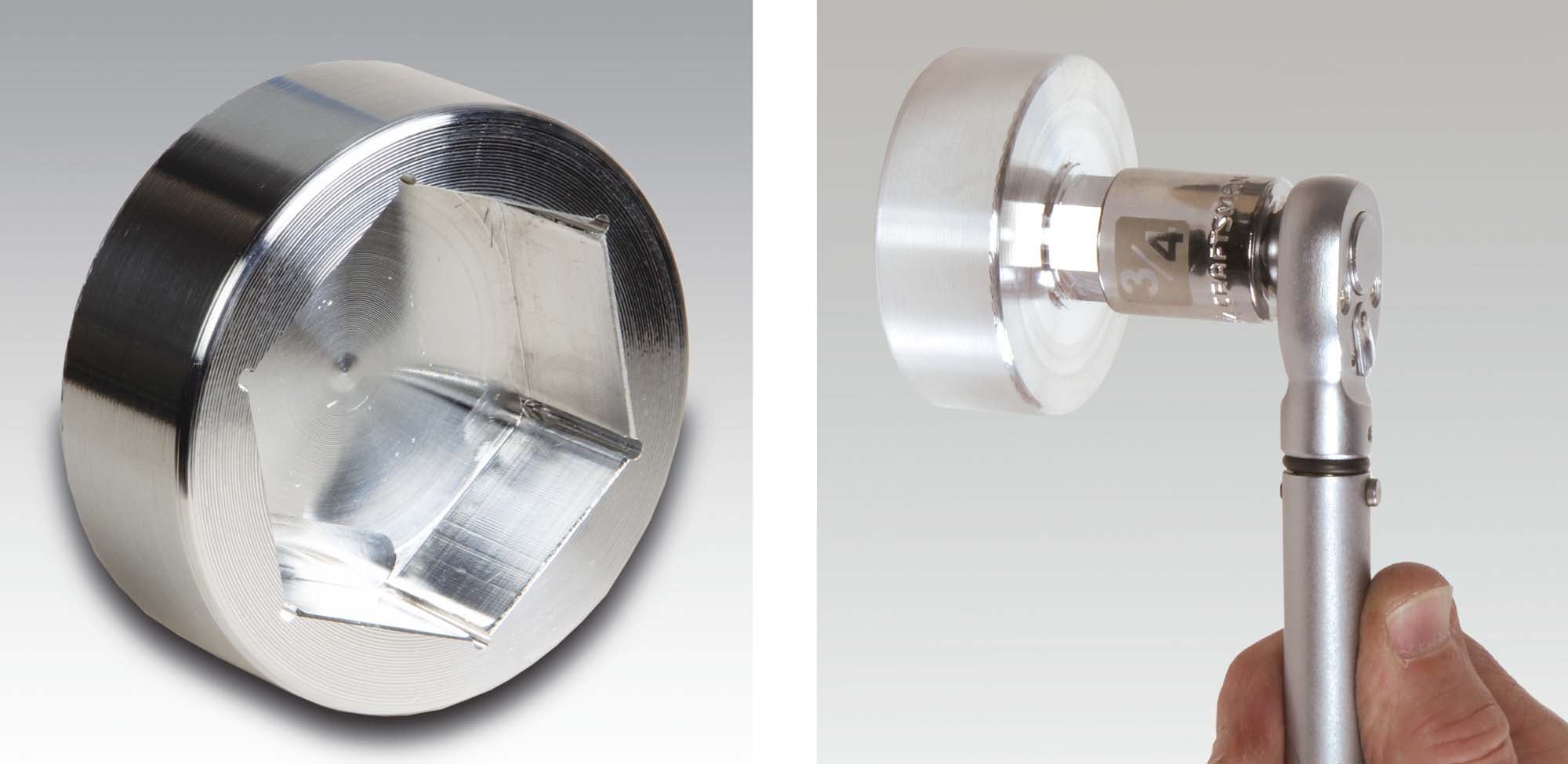
Sockets are usually steel, but when the application requires non-magnetic or non-conductive tools, you can find sockets made of brass, aluminum-bronze and even plastic. But there’s really nothing out there—at least that I could find—that fit what Aaron was looking for: a light-duty 1⅞-inch socket with a ⅜-inch drive socket. In other words, exactly the kind of project for the home shop machinist!
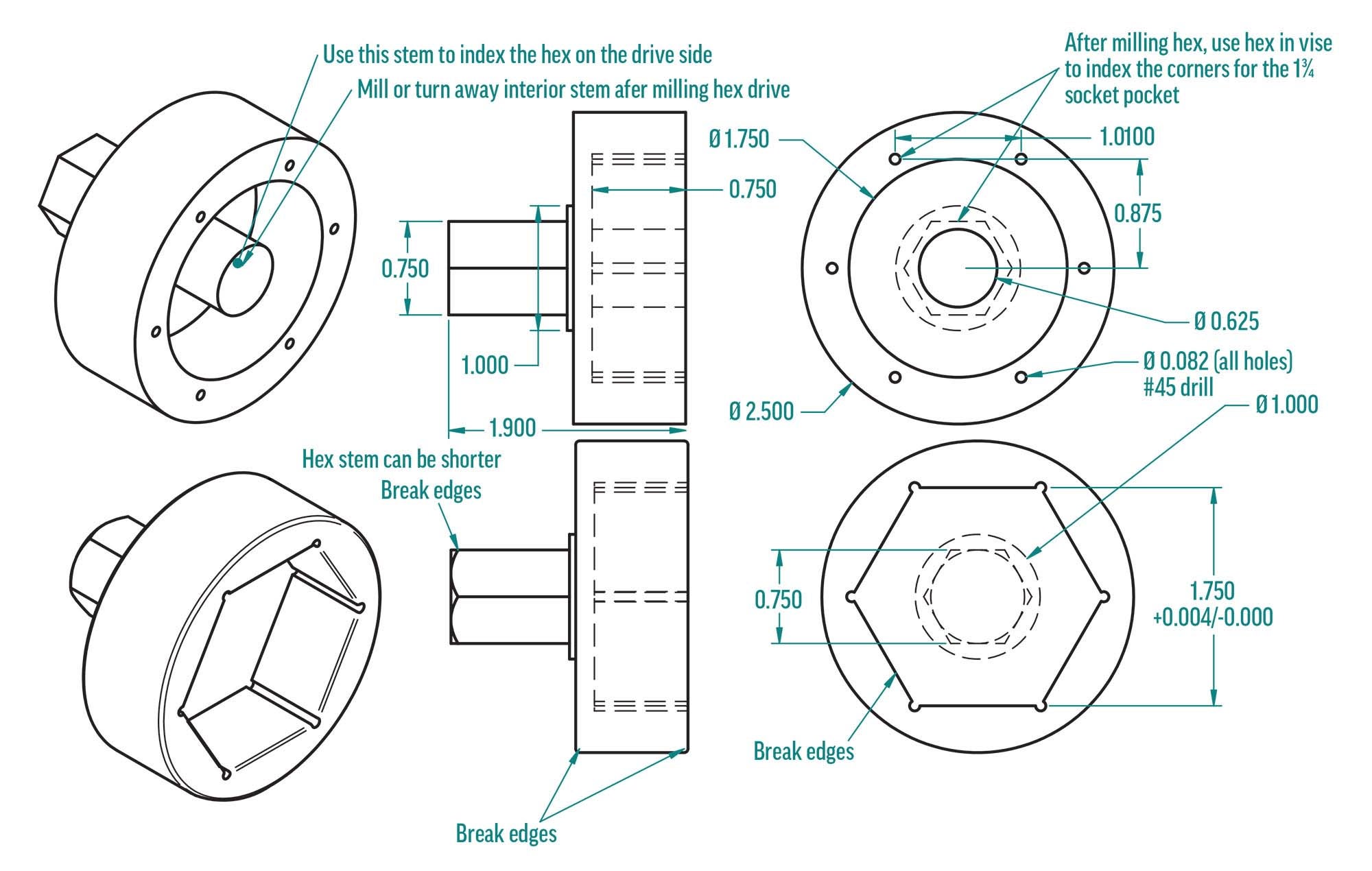
I did a quick sketch to get an idea of the machining stock needed. Since I planned on using aluminum from the get-go, I supposed it would be a good idea to make the corners of the socket a very robust ¼ inch thick. Not so much to prevent a blowout during use, but to give the tool some resilience when getting banged around in a toolbox. This drove the outside diameter to 2½ inches. The overall length was left “to be determined” because I knew the “how to make it” part of the process would have to be figured first.

As I rummaged around my collection of rems and cutoffs, I was hoping to find some 2½-inch round solid bar stock. For this project, I didn’t need much. I was thinking two inches would do it. No such luck. A couple of calls to neighbors to scrounge their bins also proved fruitless. A number of online suppliers could sell me what I needed…as long as I could wait a week! Who wants to wait a week?
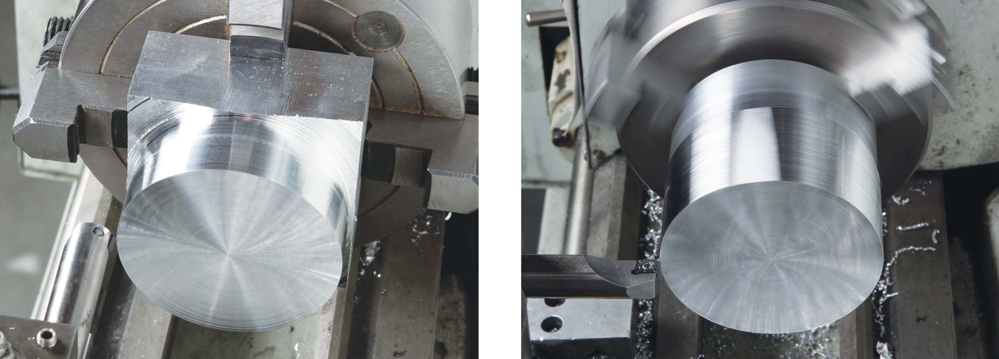
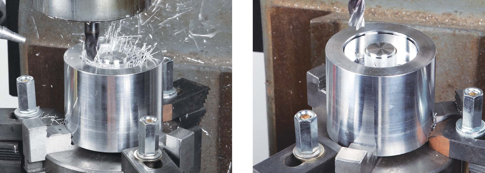

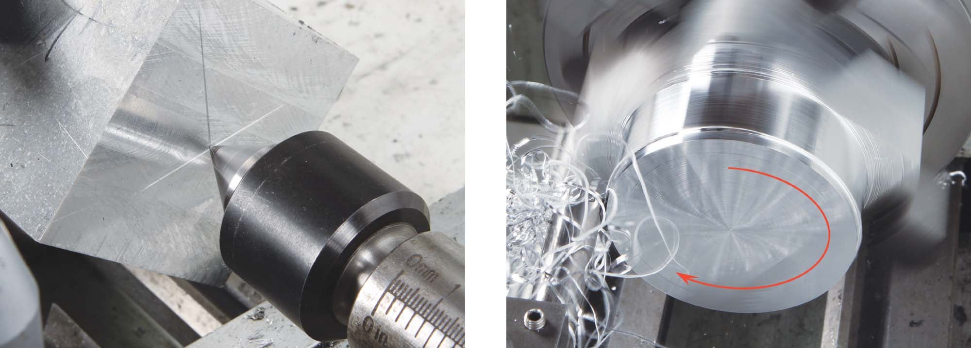
During my initial search I spied a potential “Plan B” option among the rems: a decidedly non-round slug of aluminum roughly 2½x3x2. Not a problem. After squaring up the ends on the mill, I used the four-jaw independent chuck to turn it into a round bar.
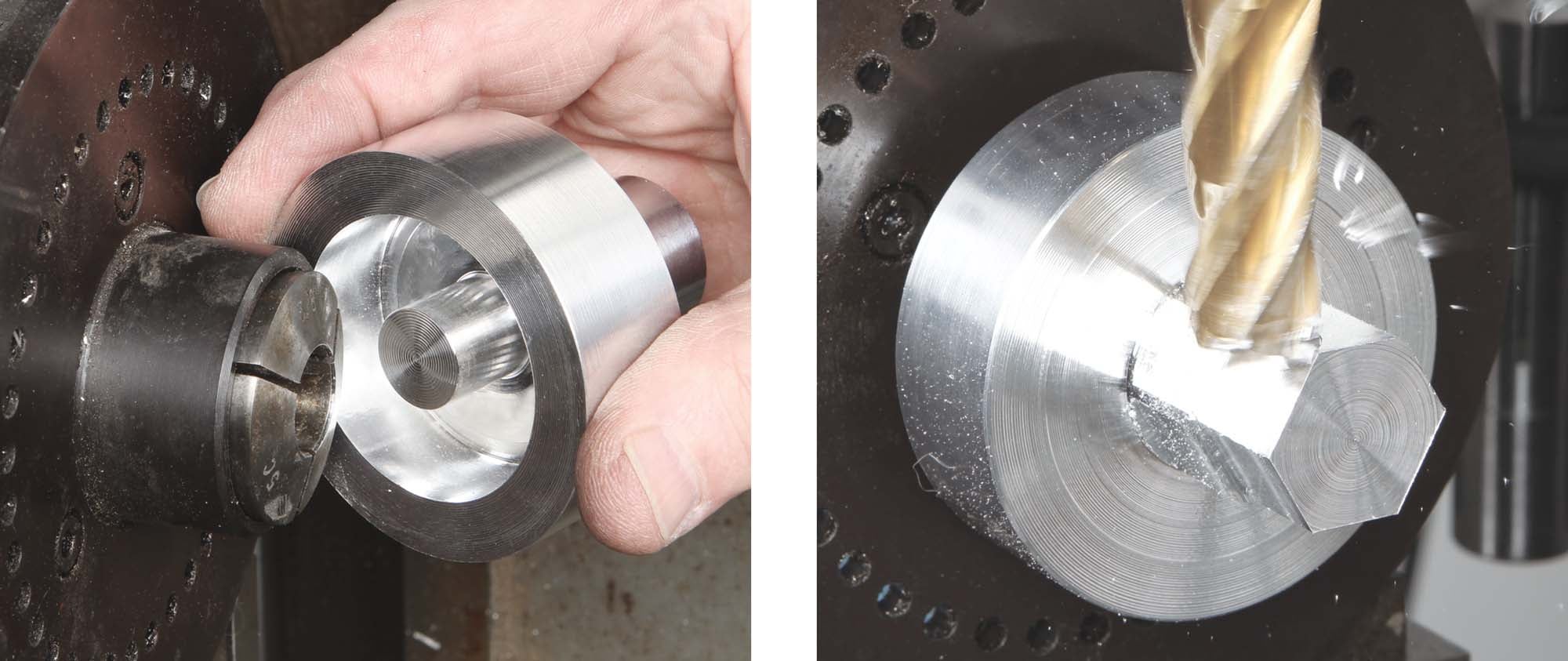
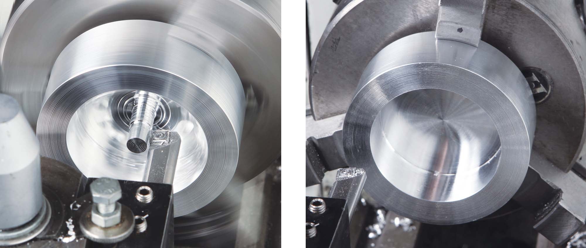
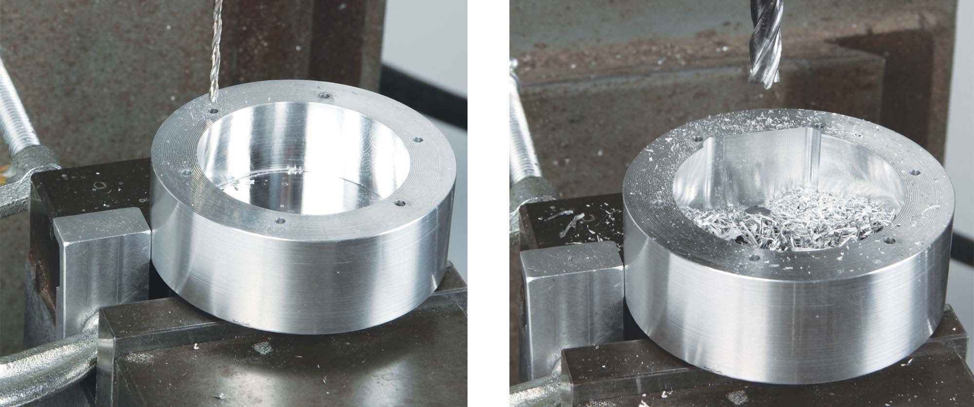
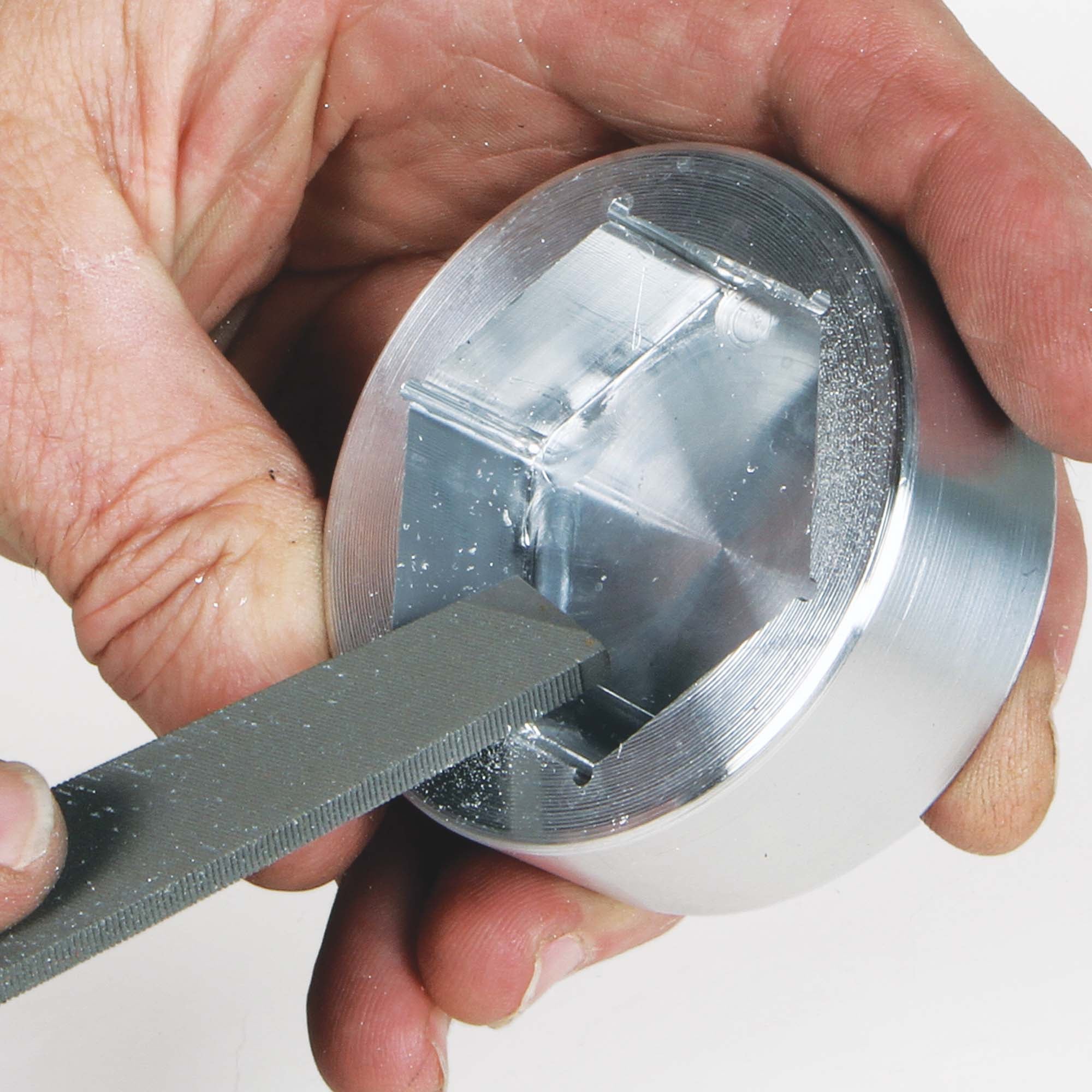
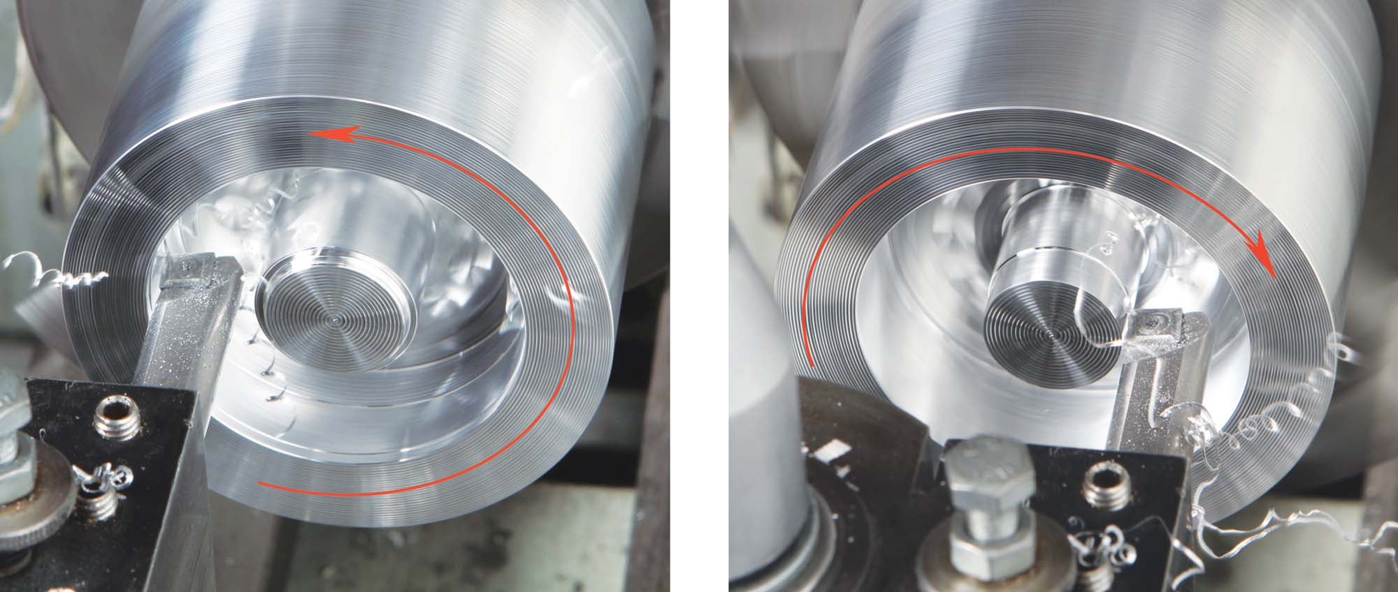
With suitable material in hand, how to make the socket cavity more or less popped into my head. By milling a ¾-inch hex protrusion on the drive end, I could use that for indexing the hex socket. Super simple, super easy. One minor problem: My blank wasn’t long enough to make a suitable length stem to use the 5C indexer to mill the designed hex. A couple of quick measurements confirmed that I didn’t need to make a protruding stem! The inside circle of the socket hex (1⅞, same as the distance across the flats) was big enough to fit over the nose of the indexer (refer to the photos). I designed a suitable clamping stem to be made during the preliminary socket cavity excavation (see drawing). The stem would be turned away after milling the hex.
If Aaron doesn’t like the idea of having to use a separate ¾-inch socket, the quick and dirty solution will be to J-B Weld a ¾-inch socket permanently to the hex drive. It won’t add much weight and it’ll never get lost. That’s it for now; time to get back in the shop to clean up the chips from this project—and there were a lot!


 Wordless Workshop")


