In our study of wing design, we have progressed from the inner portion and the flaps to the outer part of the span and the ailerons. Now we arrive at the tip of the wing.
The design of the wingtip can have a significant effect on the drag of the airplane. Wingtip design also can affect stall characteristics.
There are a large variety of wingtip concepts in use. Retrofittable tips are available for many types of airplanes, and claims of large performance improvements with specific “magic” wingtips are common.
I’m not going to review the effectiveness of any specific wingtip offered today. Material has been published comparing tips on specific airplane types, so if you’re looking to decide about a specific product, I suggest you seek out that test information.
We are going to take a look at the aerodynamic phenomena occurring at the tip of the wing and the general principles governing what makes an effective wingtip.
Tip Vortices
As the wing generates lift, it produces a pressure difference between its upper and lower surface. The air pressure on top of the wing is lower than the air pressure on the bottom. At the wingtip, the wing disappears to the air, removing the barrier between the two pressure zones.
With the obstacle of the wing surface removed, the high pressure on the bottom drives the air upward into the low-pressure region on top. Just inboard of this, the wing is still deflecting the air downward. The combination of the downwash behind the wing itself and the upward flow just outboard of the tip causes the air to wrap up into a vortex that sheds aft of the tip of the wing.
The shape of the tip affects how this vortex forms and where it sheds off of the wing.
Induced Drag
Induced drag, which is the drag associated with the production of lift, is inversely proportional to the wingspan squared. Because of this quadratic relationship between span and drag, even relatively small changes in the effective span of the wing can have significant effects on drag.
The effective wingspan is the spanwise distance between the cores of the shed wingtip vortices. A good wingtip design maximizes this distance to minimize induced drag. The goal is to make the tip vortex shed cleanly from the wing as far outboard as possible.
Wingtip Geometry
Both the planform of the tip and its cross section affect how the tip vortex forms.
The vortex sheds at or near the trailing edge of the tip. Ideally, the vortex should shed from the corner between the outer periphery of the tip and the end of the wing trailing edge, and not wrap up onto the upper surface of the wing itself.
Planform: Advancing and Retreating Tips
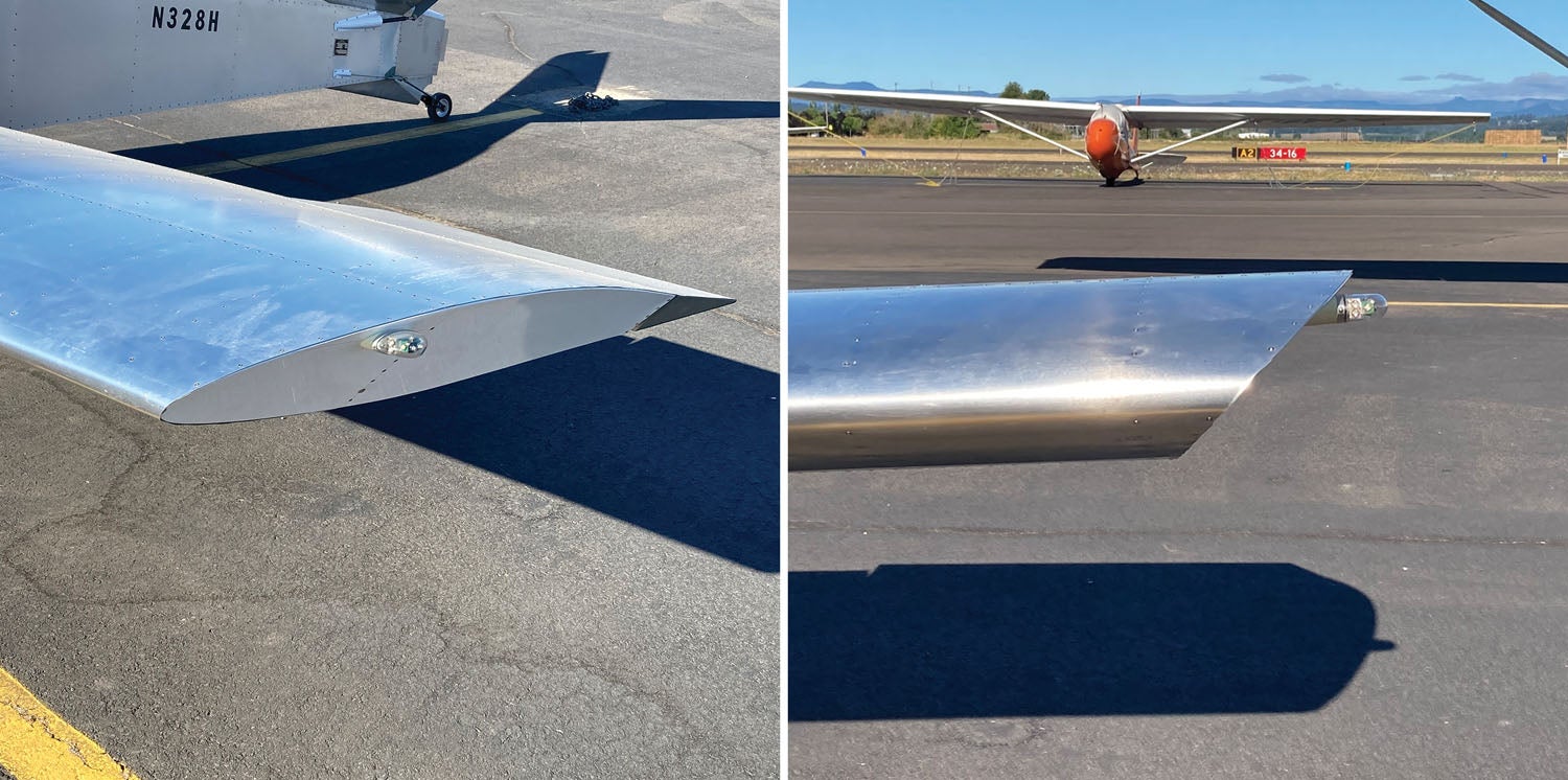
Wingtip planforms are characterized as either “advancing” or “retreating.” On an advancing wingtip, the span of the tip increases as we progress aft on the chord. The tip “advances” into airflow as we move aft. The maximum span is at the trailing edge.
On a retreating tip, the maximum span of the tip is significantly forward of the trailing edge of the wing. On some portion of the tip planform, the span is decreasing as we go aft, and the point of maximum span is not at the trailing edge.
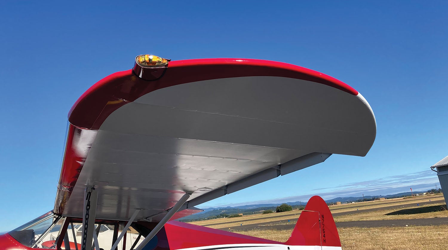
One example of a retreating tip is the classic round or circular-bow wingtip found on many fabric-covered wings such as that of the J3 Cub. These tips are popular on fabric-covered wings because the hoop tube that forms the tip effectively resists distortion from the tension caused by shrinking the fabric to make it tight.
Advancing tips tend to drive the point where the vortex sheds as far outboard as possible. They reduce induced drag and slightly increase lift as compared to retreating or constant-span tips.
Tip Cross Section
Near the tip, the high pressure from the bottom of the wing drives the flow outboard while the low pressure on the top pulls flow inboard. Accordingly, when seen from the front, there is a crosswise flow field where the air tries to flow outboard on the bottom of the wing, around the tip, and then inboard on top of the wing.
If the tip has a rounded cross section, this airflow will remain attached and will wrap around the tip and end up flowing diagonally inboard on the upper surface of the wing. The inflow will pull the point where the vortex sheds from the wing inboard and reduce the effective span of the wing.
To minimize induced drag, a good wingtip design should prevent the airflow from wrapping around the tip. Ideally the flow should separate cleanly from the wing at its outermost point and depart from the wing with a slight outward velocity component to force the tip vortex outward.
The way to achieve this is to treat the outer periphery of the tip as the crossflow equivalent of an airfoil’s trailing edge. If the outer edge of the wingtip is sharp like a trailing edge, the outward cross flow on the lower surface of the wing will separate at the sharp edge and not wrap around the top of the wing.
This will generate an outward component in the crossflow as the air tries to flow around the wingtip and is forced to separate from the tip at the point where it has the maximum outward velocity. This outward crossflow tends to force the core of the tip vortex outboard and will increase the effective span of the wing and decrease induced drag.
Tip Geometries
Advancing Tip
As we can see from the preceding discussion, a good tip geometry is an advancing tip with a sharpened outer edge. The cross section of the tip should progress from rounded near the leading edge as it transitions off the nose of the airfoil to sharp farther aft. The sharpened portion of the outer edge should be highly swept so that once the sweep of the tip planform exceeds 45° to 60°, the transition from round to sharp cross section should be complete. The aft portion of the outer edge should remain sharp all the way back to the trailing edge of the wing.
“Slashed” or “Chopped” Tip
A very simple wingtip design that works relatively well is a tip formed by simply cutting off the tip of the wing at an angle in the front view. On a metal wing this can be accomplished by canting the outermost rib outward so the intersection between the rib and the upper wing skin is outboard of the intersection with the lower wing skin. While a tip like this is not quite as effective as the properly shaped advancing tip described above, the sharp edge between the upper wing skin and the canted tip rib does encourage the vortex to shed outboard, making this tip design significantly better than simply chopping the end of the wing off square.
Slashed tips like this also work well on propellers and can produce a small but measurable improvement in propeller efficiency.

Things to Avoid
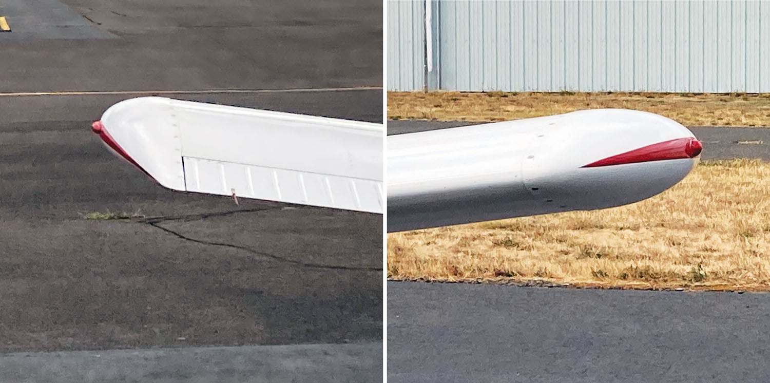
Any tip that has a fully rounded cross section from the front view will tend to pull the tip vortex inboard, increasing induced drag and reducing lift.
Retreating tips are generally inferior to advancing or slashed tips.
One tip design that appeared on several production airplanes that combined both of these poor features is a “teardrop” shape formed by blending the upper and lower wing surfaces with circular cross sections with a diameter the same as the local airfoil thickness.
There are a variety of wingtips and wingtip devices that are used to try to gain an advantage over what the tips we discussed this time offer. These include tip droop, end plates and winglets, all of which will be our subject for next month.


