In the last few months, we have explored how planform and taper affect both the distribution of total lift across the span and the weight of the wing structure.
Last month we saw how tapering the wing moves the centroid of the wing load inboard, reducing bending moment at the root and also how taper makes the spar deeper at the root. Both of these factors reduce the structural weight of the wing.
In terms of aerodynamic efficiency, we also saw that properly tapered wings have a span loading that is closer to elliptical than a constant-chord wing. Accordingly, tapered wings will have a higher span efficiency and lower induced drag at the same span and total lift.
All of these factors infer that tapered wings should be the obvious choice for a designer. The situation is not that simple, however.
While pure structural considerations may suggest a wing with a pointed tip or very high taper (small tip chord i.e., small taper ratio), there are limits to this. If the wing is tapered too much, it becomes excessively root loaded and its span efficiency deteriorates. Also, as we will see soon, highly tapered wings tend to stall from the tips inboard, which can produce very unpleasant stall characteristics.
The range of taper ratios for good tapered wings runs from approximately 0.5 to not smaller than between 0.2 and 0.25. Note that this is true only for wings with aspect rations higher than about 2.5. Low aspect ratio wings behave differently. While this is a subject very dear to my heart, today’s discussion is for more “conventional” wing aspect ratios.
Lift Coefficient Distributions
Up until now, we have been looking at the distribution of absolute lift across the span. We now turn our attention to the distribution of local lift coefficient over the wing.
The local lift coefficient is the local lift per running distance divided by the local wing chord and the dynamic pressure of the airflow.
Accordingly:
Cl=l/(q C) at every point along the span
Where:
l = local lift per running distance
q = dynamic pressure
C = local wing chord.
(Note that this is a local 2-dimensional lift coefficient as opposed to the full-wing 3D lift coefficient that is computed using total wing lift and wing area.)
On a constant-chord wing the distribution of lift coefficient has the same shape as the distribution of gross lift. The lift at each station along the wing is normalized by the same constant chord and dynamic pressure to get a lift coefficient, so the distribution scales by a constant factor when going from lift to lift coefficient.
This is not the case for a tapered wing.
On a tapered wing the chord varies along the span, so local lift is normalized by an ever-smaller chord as we move outboard. Also, the individual sections of the wing are not working in isolation. Each is influenced by the flow over the rest of the wing.
On a tapered wing this interaction makes the shorter-chord, outboard portions of the wing work harder. Although the lift is shifted inboard by the taper, it doesn’t shift inboard as much as the change in chord alone would indicate. This means that as the wing becomes more tapered, the lift coefficients of the outer portions of the wing increase and those of the inner portions decrease relative to a constant-chord wing of the same area and span.

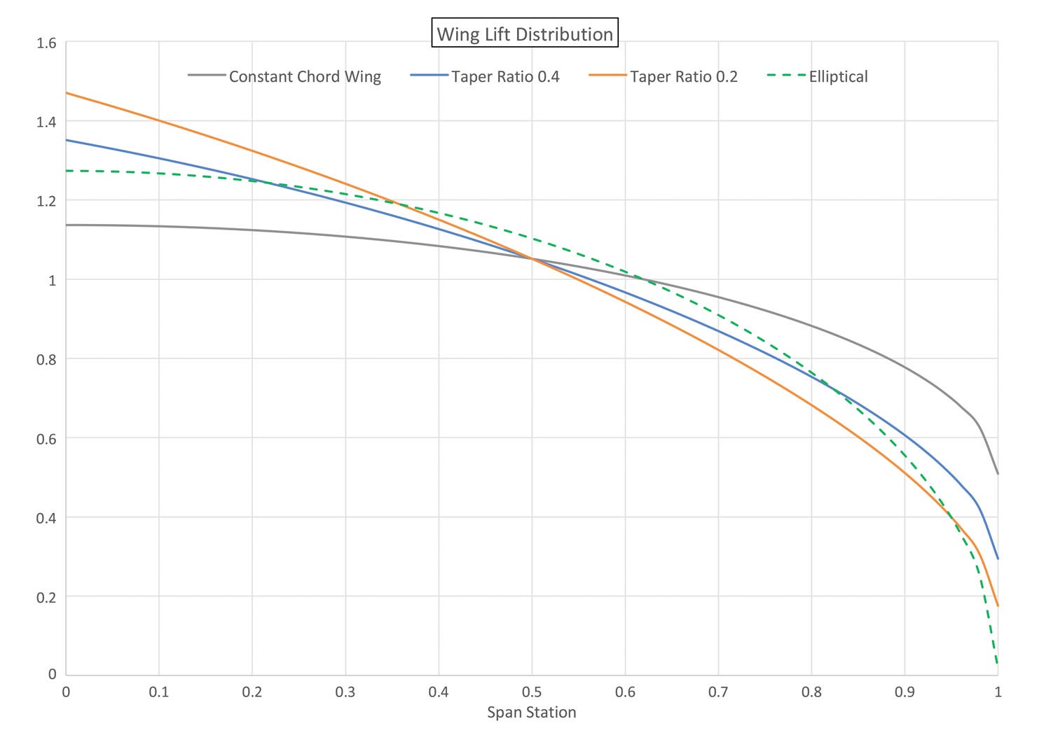
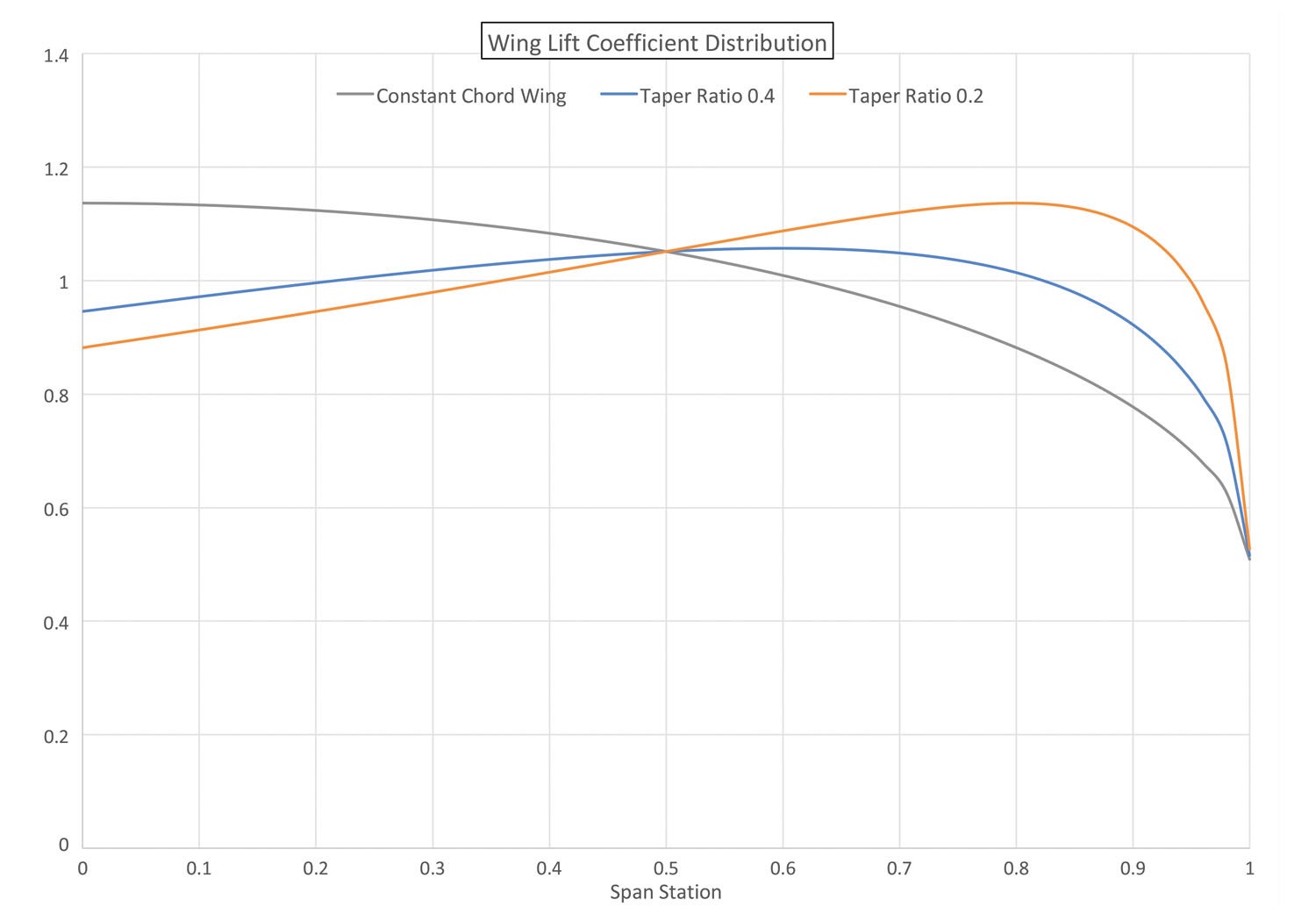
Figures 1 and 2 illustrate this effect for three example wings:
- Constant chord
- Taper ratio = 0.4
- Taper ratio = 0.2
Figure 1 shows the spanwise distribution of lift for all three wings. As we discussed in previous months, as the wing becomes more tapered (smaller tip chord, lower taper ratio) the lift shifts inboard as the long-chord inner portions of the wing carry more total load than the shorter-chord outer parts. We can also see that by the time we get to 0.2 taper ratio, the outer portion of the wing is significantly unloaded compared to the less-tapered planforms. The lift has shifted enough away from the elliptical distribution shown by the dotted curve that the span efficiency of this wing is starting to suffer compared to the less-tapered (taper ratio 0.4) wing. This means that while the taper ratio 0.2 wing might have a structural advantage over the taper ratio 0.4 wing, that advantage must be traded off against a loss of aerodynamic efficiency.
Figure 2 shows the spanwise distribution of lift coefficient (Cl) for the same three wings generating the span loads shown in Figure 1. We can clearly see how the outer portions of the tapered wings are being called upon to carry more lift per unit of chord than those of the constant-chord wing and how tapering the wing amplifies this effect even more.
This has serious implications for the stall characteristics of the airplane.
Notice that the maximum local Cl for the constant-chord wing is at the root.

For the taper ratio 0.4 wing the maximum local Cl for the constant-chord wing is at about 60% of the semi-span, while for the taper ratio 0.2 wing it is near the tip.
Where the stall starts on the wing is very important for the safety of the airplane.
Although a detailed description of stall characteristics will be left to a future article, it’s important to note that for safe stall characteristics it is highly desirable to have the stall form initially at or near the root of the wing.
If the stall begins further outboard than about 1/3 of the semi-span, the airplane is likely to exhibit roll instability at the stall. It will have an ever-increasing tendency to depart controlled flight laterally and spin as the point of initial stall moves outboard. This tendency is exacerbated by the fact that when the stall starts outboard on the wing, the initial stall is likely to kill off the effectiveness of the ailerons or, in extreme cases, might even lead to aileron control reversal.
Summary
Overall, a constant-chord wing can be expected to have more benign stall characteristics than a tapered wing.
For tapered wings, we can see that there is a “sweet spot” of taper ratio to get the maximum benefit of taper. Up to a point, tapering the wing improves span efficiency, thus reducing induced drag. It also makes the wing more efficient structurally, which saves weight.
If we taper the wing too much, it can cause problems.
Tapering the wing also moves the point of maximum local Cl outboard, which raises issues with roll stability and controllability at the stall. These issues increase with increasing taper. Also, tapering beyond a certain point alters the lift distribution in a way that increases induced drag.
At this point, we understand some more of the trade-offs inherent in the choice of wing planform, but we are not done yet. Up until now we have been discussing characteristics that are purely due to the planform shape of the wing. Next month, we will take a look at how introducing twist to adjust the lift distribution and stall characteristics affects our wing design.


Thank you for writing this column, I look forward to it each month.
Hello,
I see that you have created these distribution graphs on MATLAB. Would you be able to share the code for these? I want to see the local lift coefficient distribution for the wing I am designing for a student team. It has a rectangular section and an outer tapered section so it is tough to find literature data for it. I will not share the code with anyone if you would be so kind to give me a copy.