As we saw last month, the designer has two fundamental choices of wing structural architecture: cantilever or externally braced. In a cantilever layout all of the loads on the wing are borne by structure inside the airfoil contour of the wing itself. Braced wings use additional structural elements that are external to the wing contour to help carry the load.

The way the loads are carried in the structure and the way the wing structure integrates with the fuselage are fundamentally different for the two architectures. This month we’ll take a closer look at externally braced wings.
Wing Bending Moment
A wing develops lift along its entire length. This means that the centroid of the wing lift is well outboard of the root. A large portion of the weight of the airplane is in the fuselage. This means that the lift acting outboard reacts against the weight carried inboard. The offset between the two opposing forces causes a bending moment about the root of the wing that tries to make the wing flap upwards in upright flight. The structure of the wing must transmit the lift to the weight and also resist the bending moment.
Lift forces are reacted at the wing root as vertical shear. The bending moment is resisted by compression in the top elements of the wing structure and tension in the bottom ones.
On a cantilever wing these forces are carried in the upper and lower spar caps, and the wing has only the depth of the spar between these opposing reaction forces to develop the moment required to resist wing bending.
External Structure
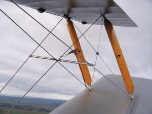
A braced wing uses external structural elements to help carry wing loads. These external elements can be either struts that are rigid and can carry both tension and compression loads, or wires that can only carry tension.
The advantage of braced wings is that the introduction of an additional bracing element to the structure allows the structure to take advantage of the vertical distance between the attach point of the wing root and the attach point of the bracing element to resist wing bending. This distance is much greater than the thickness of the wing, and the tension and compression forces in the structure needed to resist bending are proportionally smaller. This makes the wing structure lighter and stiffer than a cantilever structure.
Wire Bracing
Early airplanes were almost exclusively wire-braced. Since wires only carry tension, the structure needed separate wires to bear the upward and downward loads on the wing. The “flying wires” carry positive lift loads, and “landing wires” handle inertial droop loads on landing and negative lift in inverted flight or in a down-gust.
The biplane layout is well suited to this since the wires can be arranged to form the diagonal elements of a bridge-like box girder structure. By using multiple bays with sets of interplane struts, the wires can be kept relatively short and placed at favorable angles relative to the imposed load.
It’s harder to effectively wire-brace a monoplane wing since all of the wires must go directly to either the fuselage or a fuselage-mounted strut system. This is less structurally efficient than the crisscrossed wires of a biplane and may help explain why early designers tended not to see any significant advantage in a monoplane configuration.
In today’s world wire-braced wings have virtually disappeared, except for ultralights where weight saving is critical. It’s possible to make a very light wire-braced wing, but the trade-off of weight against the high drag of the wires and the complexity of multiple wires and attach points only comes out positive if weight is a primary concern and drag isn’t.
Strut Bracing
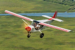
A strut-braced wing consists of a main wing with internal spars braced by either a single strut or a pair of struts. The number of bracing struts depends on the internal layout of the wing itself.

A classic fabric-covered wing like the wing of a Cub or Citabria has two spars connected by ribs that support the fabric. The fabric itself contributes very little to the strength or torsional stiffness of the wing. Because of this, such wings have two main lift struts, one for the front spar and one for the rear. The two-strut arrangement carries the lift loads and stabilizes each of the spars so they do not bend significantly differently as a result of torsional aerodynamic loads.
On a metal-skinned wing like those found on the classic Cessna singles like the 150 and 172, the wing skin combines with the spars to form a torsionally stiff box structure. A wing like this can be braced against lift-induced bending loads by a single strut.
The spars of a strut-braced wing do have to resist some bending moment. The portion of the wing outboard of the strut attach point acts as a cantilever structure, but the combination of the smaller total area and shorter length of the outboard portion of the wing means that the bending moment at the strut attach point is much smaller than the bending moment at the wing root.
The portion of the wing between the root and the strut attach also carries lift, so it can have reversed bending moment near its center as the lift tries to raise the wing between the constraints of the root and strut. This causes the center of this portion of the wing to try to rise between the constraints and the wing itself to try to bend down at the root and strut.
The total wing “flapping” moment at the root is reacted by compression in the wing spar and upper carry-through elements and tension in the strut and lower carry-through elements. (Note: This is for a high-wing airplane. On a low-wing, strut-braced configuration, the strut is in compression and the wing spar is in tension).
The net bending moment on the wing spar where it attaches to the fuselage is zero, and both the wing and the strut can be pin-connected to the fuselage. The wing root attach fittings need to carry tension or compression as well as shear, but do not have to carry bending moments.
Fuselage carry-through is loaded in pure compression on top and pure tension on bottom. Because these elements are relatively short, even the compression elements on top do not have to be very deep to carry the load and be structurally stable.
Advantages and Disadvantages
The high-wing, strut-braced wing configuration offers two primary advantages over a cantilever wing. The first is weight. The spar caps of a cantilever wing are highly loaded because the structure has only the depth of the wing between them to resist the wing bending moment. This means they need a relatively large cross section to carry the load and will accordingly add significant weight to the structure. The same is true of the wing carry-through structure, which must continue to carry the bending load all the way across the fuselage.
Because the strut-braced wing has the full depth of the fuselage over which to resist wing bending moment, the loads in the structural elements (wing spar, strut, carry-through) are much lower than in a cantilever arrangement, and the combination of wing and strut will be significantly lighter than the equivalent cantilever wing.
The second advantage of the strut-braced wing is integration of the fuselage. A cantilever wing must have a full-depth carry-through structure. This can cause issues in the layout of the cabin, particularly on single-engine light airplanes where the crew is seated near the center of gravity. The wing spar, which carries the weight of the airplane must also be near the CG to get the proper relationship between the lift and the weight of the airplane for stability and control. Because of this, the wing spar and the crew tend to want to occupy the same space. On a cantilever arrangement, the occupants of the airplane must sit either over or under the wing carry-through.
On a low-wing airplane, the spar can run under the seats or under the knees without increasing the depth of the fuselage too much. The problem is harder on a high-wing arrangement because the spar must run either behind or over the occupant’s heads, even if the spar is actually forward of the pilot’s eyes. It must be high enough up so the pilot can see forward and up past the spar.
Strut bracing the wing solves this integration problem because the people can sit between the tension elements running across the bottom of the fuselage and the compression elements running across the top. Particularly for high-wing airplanes this is highly desirable since it makes visibility better and allows the fuselage to be shallower than it could be with a cantilever wing.
The primary disadvantage of any externally-braced wing is that the bracing elements, be they struts or wires, are exposed to the airstream and generate significant drag. On early wire-braced wings with circular cross-section wires, the bracing wires actually produced more drag than the wing. On a strut-braced wing with a properly streamlined strut cross section, the struts themselves produce drag approximately equivalent to that of a section of wing that has the same wetted area as the strut. There is some additional drag penalty due to interference of the junctions at the ends of the strut. This can be partially alleviated by well-designed junction fairings.
Strut-braced wings are a good design option for airplanes where absolute maximum cross-country performance is less important than takeoff distance and load-carrying ability. Many utility and bush-flying airplanes are high-wing, strut-braced machines for this very reason.


