Several times over the many years I’ve written a column for this magazine, I’ve told you about a computer program that makes very complex PC boards, all the way from the first rough sketch on the proverbial back of a napkin to the formula for the etchant of the excess copper on the fiberglass PC-board substrate.
Twenty-four years ago, a very refined version of CircuitMaker/TraxMaker was released and was nicknamed CMTM2K (CircuitMaker TraxMaker 2000). Several particularly noxious bugs were replaced with elegant solutions to the program, and it has been my go-to (for the last 24 years) when I wanted to make a prototype PC board.
In 2001 I came by this relic of an elderly 1958 Cessna 182A that I rescued literally from chickens roosting on the rear seat and the wings in a farmer’s barn rafters. Total disaster. Nothing to do but to rip out all the innards (including the wiring) and start from scratch. It may not qualify as a homebuilt, but not a stitch of fabric or a centimeter of wire remained inside. It was then coated inside and out with zinc chromate and painted with the best automotive paint I could find.
But I digress. It also got completely new wiring along with some new and some upgraded avionics. The documents I got with the paperwork were sketchy as to the old wiring, so this was going to be a project from scratch. The saving grace was that this was a two-year project and by the time I got around to doing the wiring, CMTM2K had been released. Even better, the authors of CMTM2K named me a beta tester and authorized me to distribute it to anybody I thought would help work out the bugs in the program.
I drew the electrical system of the airplane totally with CMTM2K. I tell you right now, each and every wire, each and every connection and each and every pin got a name, a number and a place in the wiring package, and it remains today in my 182 aircraft documentation both in print and digital format. You can have your own full copy of CMTM2K, including all updates and a full manual, at www.rstengineering.com and then to CMTM2K. It’s a 45MB file, so it may take a while.
The problem, of course, is that a PC board layout program has no need for alternators, starters, nav/coms or ADS-Bs, so those devices had to be added to the library. Piece of cake. CMTM2K allows you to make as many new devices as you wish with as many pins as you wish. Takes you 10 minutes to make a relatively complex new “part.”
The rest of this column will explain why these “homemade” parts (done the way the downloaded manual describes) let you draw your homebuilt electrical system to your heart’s content.

What Does It All Mean?
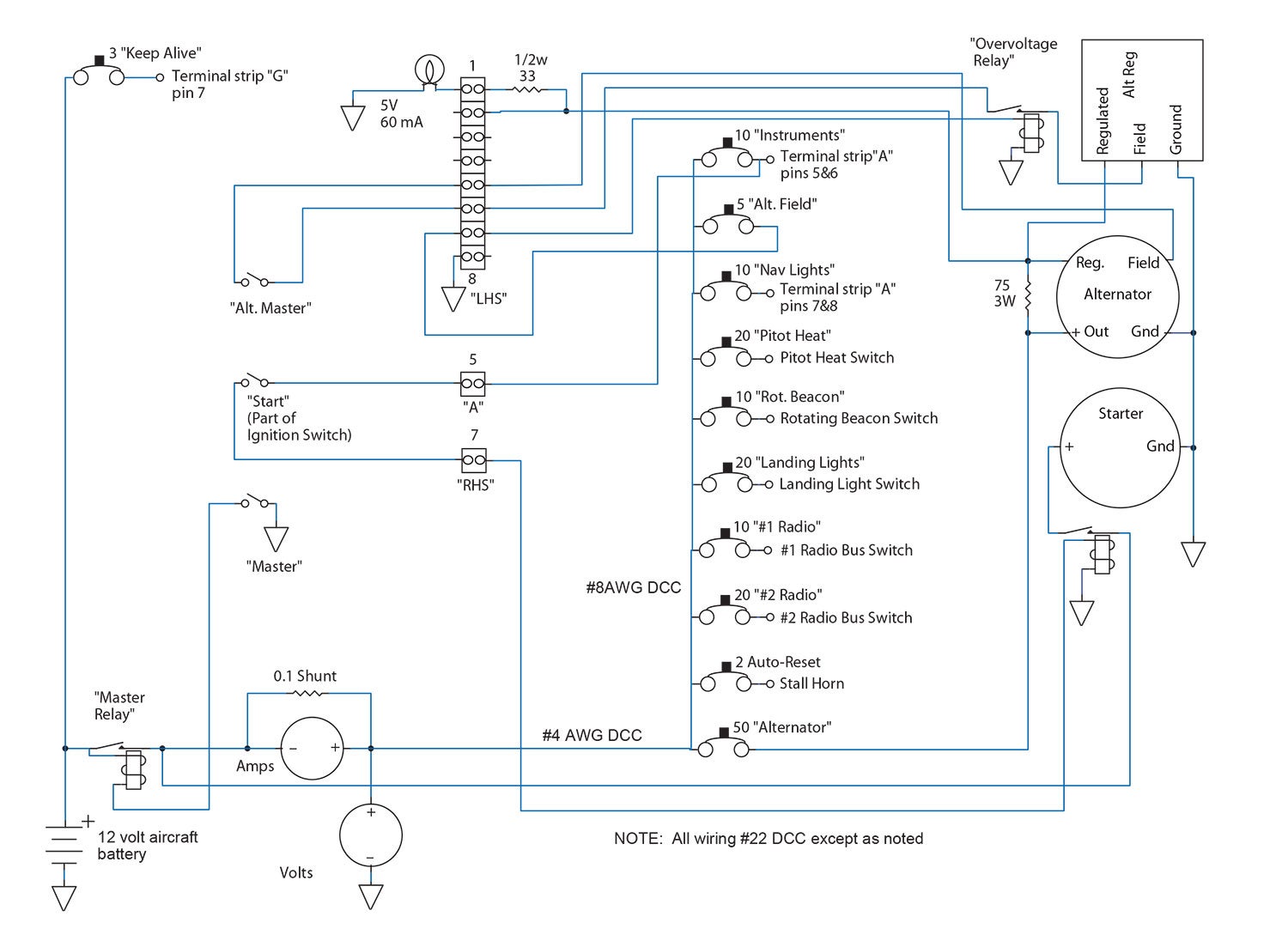
Let’s take a look at the drawing. What a spaghetti diagram! Not really. Let’s start from left to right.
That little symbol in the upper right-hand corner is a 3-amp “keep alive” circuit breaker, which is what the FAA allows directly from the battery without a master Battery On switch. It is generally used for a clock or other device that draws a small amount of current but shouldn’t need to be reset on every flight.
To its immediate right is an 8-pin screw-type terminal strip for connecting wires that may need to be reconnected someday. Pin 1 at the top is a 5-volt incandescent bulb connected by a half-watt 33-ohm resistor to Pin 2.
Pin 2 is connected by a wire to the “Reg” connector of the alternator. Just before it connects to the Reg connector, it has a small dot on another wire to a 75-ohm resistor and another wire headed up to the Regulated terminal of the voltage regulator. That little dot means that those two wires are connected. (Sloppy work, Weir. How am I supposed to know 23 years later that the square box in the upper right-hand corner is the voltage regulator? Deduct 10 points from your score.) As a contrary example, note that the same wire from Pin 2 crosses a wire to the overvoltage relay but without a dot. When two wires cross without a dot the wires are not connected.
Flow is not always from left to right. Note that the alternator output is connected to the aircraft battery through the ammeter and master relay directly to the battery.
There are 10 such sheets in the N73CQ file, one for each instrument or radio in the aircraft. Changing an instrument or a radio? No big deal. Just take the schematic file for that particular device and change it to reflect the electrical change. Of course, there will be a notation in the regular logbook of the weight and balance change, yes? Please?
There are some items that may show as a “wire” on the schematic but may not technically be a physical wire. Both the alternator and the starter show a wire going from the Gnd (ground) terminal to what we affectionately call “ground.” Universally in a metal ship, “ground” is the metal airframe, so these two large items have bolts to the airframe engine (and then through the mount) to the airframe. Likewise, the battery is shown with the (-) minus terminal grounded. There’s also a bolt and terminal to the airframe close to the battery. In fabric and glass ships, this “ground” is not so well defined, and each designer has chosen their own personal way of making sure that each grounded device has an extremely low resistance to all of the other grounded devices.
Why is this so important? With a metal aircraft that is properly riveted together, all of the metal sheets are like very small resistances in parallel, which gives very, very small resistances from the tail feathers to the spinner. Very small resistances give very little heat and concomitantly very little voltage drop and very little heat generated. However, in a fabric/glass ship there needs to be one very large conductor from the battery to the rest of the aircraft. Why? Heat.
Let’s presume a 12-volt battery behind the baggage compartment and the starter on the back of the engine. Let’s also presume the designer isn’t as well up to speed on Ohm’s law as you and I, and he takes a #10 wire from battery to engine—about 1Ω. When the starter kicks in, it draws 100 amps. Now P=I² x R, so that wire is going have to dissipate about 1002 x 1 or 10,000 watts. That’s going to melt a lot of plastic and set a lot of fabric on fire, so we now have to balance putting in a fatter wire (more dead weight) and heat reduction.
Here’s a little teaser to end this month’s column. If any of you can tell me why the 182 was renumbered 73CQ, you’ll receive a hundred bonus points. More later. Until then…Stay tuned…


You have a very apt callsign, Mr. Weir.
73: Best regards
CQ: calling anyone, i.e., general call
So 73CQ is essentially saying “Best regards, everyone!”
73, W3RFF
73 is the year you graduated from High School. You are also an amatuer radio operator. CQ is what amatuers say when they are seeking open dialogue with any other amateur.
FB OM on N-number.
73, KD5NRO
“73” – Best wishes to another Ham Radio Operator.
“CQ” – Call for contact to any other Ham
And thanks, for not making “73” plural!
I would have to say that you aren’t really as “…up to speed on Ohm’s law…” either. If you try to draw 100 amps through a 1 ohm wire from a 12 volt battery you can’t get 100 amps. The most possible would be 12 amps (I=E/R – 12A = 12V / 1 ohm) which means the power dissipated would be only 144W, not 10,000W – still a lot of power and not good for the wire.
If you are going to write articles explaining electrical projects, please get someone to proofread them before publishing..
Man, did I blow it out my @$$ on that one. I suppose I could claim stupidity, but after teaching it 40+ years as a Community College prof, and 40 years of writing KP columns, this one comPLETEly slipped by me. Thanks for pointing it out. I deserve 40 lashes with a wet piece of RG-174. Thanks for the catch.