 In the last article I wrote briefly about builder’s block and the many different forms of it. The builder’s block that hit me most recently was one that has a builder just looking at their project for days and scratching their head while trying to figure out how to make the next steps of a customization work.
With this Zenith that I call 750SDXtreme, I have decided that the “Xtreme” is the amount of time consumed doing modifications that might only add very little benefit to the flying airplane when it is compared to an airplane that was built with standard kit components. You have heard me say it before and I will continue to say it that the best approach is to just build the airplane to the factory specs and fly it. This is especially true if you want to be flying it on a reasonable timeline. That said—and now that the exhaust modifications from my last article are complete—it’s time to figure out how to help the engine breathe cool air in this 750SDX.
About the Turbo
The ULPower 520T aircraft engines utilize a turbo system to compress the air and increase the intake air density so the engine can make more power—in this case, 220 hp compared to the 200 available with the non-turbo versions of the six-cylinder powerplant. In traditional aircraft engines, there have been two ways to get more power and maintain it at altitude. Highly boosted engines offset a lower compression ratio with more turbo boost than the standard of 30 inches of manifold pressure. (That’s the assumption you make when you’re at full throttle on a sea-level day with a non-turbo engine.)
The other tactic is called turbo-normalizing, where the engine retains a compression ratio commonly used without a turbo and the boost is limited to 30 inches, though sometimes it’s a bit more to compensate for power-sapping higher induction-air temps. This tactic was popular when there were add-on turbo systems for airplanes because you didn’t have to change the core engine.
The ULPower 520T is somewhere in between. It does have a lower compression ratio than the non-turbo versions—8.0:1 instead of 8.7:1—and is rated for a maximum of 38 inches of boost. So it’s not as highly boosted as some turbocharged engines but not exactly turbo-normalized in the conventional sense.
Power is the goal and the 520T has it. From just 5254cc (321 cubic inches), the engine makes 220 hp with direct drive. It takes a much heavier four-cylinder Lycoming 390 cubic inches to get close. Better yet, the 520T makes its full 220-hp rated power to 15,000 feet.
For low-level flying here in Tennessee, the turbo doesn’t have to work all that hard, but as altitude increases, the turbo works harder to compress the intake air for the engine. The only performance downside to this boost is that while the intake air is compressed, it is also being heated; hot intake air does not help engine power, performance or reliability.
Intercooled
ULPower recommends an intercooler to reduce intake-air temps. Think of the intercooler as a radiator for the induction air. In most aviation applications, the intercooler is what we call an air-to-air type, which simply means that air is passed across a set of fins, just like in a coolant radiator or an oil cooler, while the intake air is passed through inside. Think of the induction air like coolant or oil in those other examples. The intercooler resides between the turbocharger’s output and, in the case of the ULPower, the throttle body.
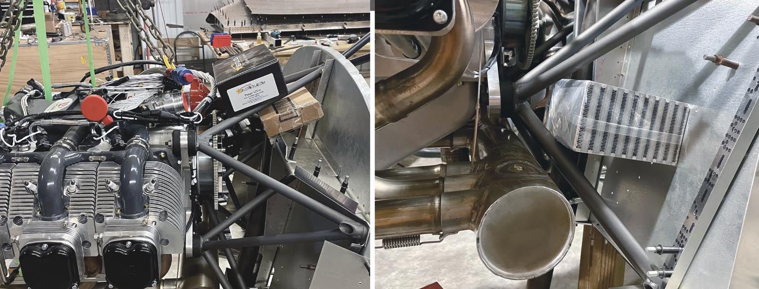
My basic requirements are to use a simple air-to-air intercooler. However, “simple” does not seem to fit into my 750SDXtreme build because of the space limitations stemming from my custom short engine mount (discussed in Part 8, found in the December 2023 issue). I knew things were going to be tight once I decided to move forward with the custom engine mount, but I may not have realized just how ridiculously tight things were actually going to get—and it is only going to get worse as I start installing all the necessary firewall forward components.
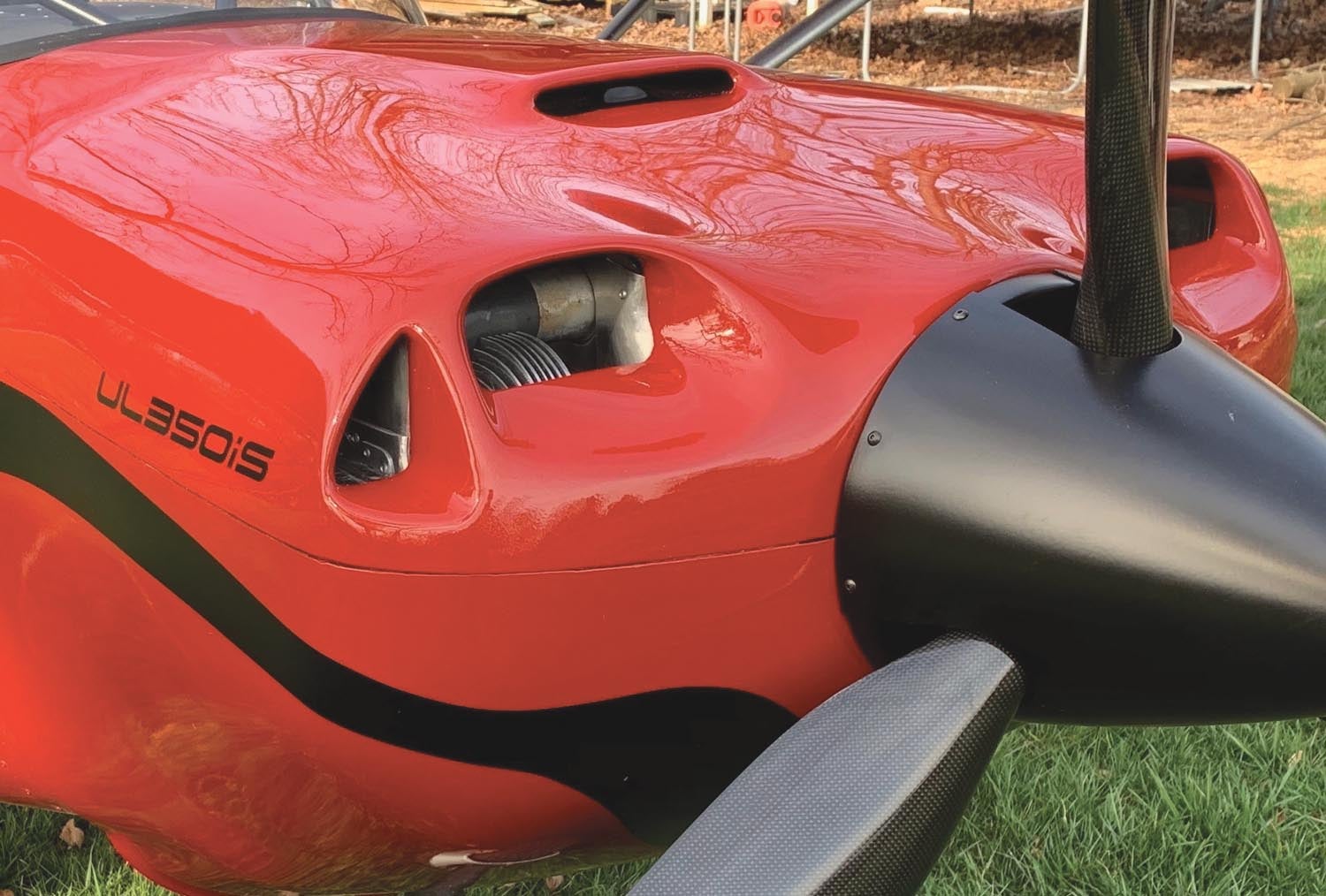
My first intention with the intercooler location was to mount it above the top engine mount tubes and incorporate a cowl scoop (similar to the scoop on my Super701) to feed the intercooler. While this was possible, it became quickly obvious that the cowl scoop would have to stick up substantially from the cowl and it would block my view forward. Since one of my goals is having even better visibility than my Super701, I cannot bring myself to incorporate a large/bulky scoop on top of the 750SDX cowl. So now I have a dilemma and an engineering challenge.
Once I got more specs from ULPower and a few intercooler companies, it was time to make a decision of what size intercooler core to use. I decided to go with a Bell bar-and-plate-style intercooler core and I went slightly oversized from the specs I was quoted because I absolutely do not want the intercooling system to be an intake restriction that could rob power. The possible advantage of going oversized is slightly better cooling and breathing than what is recommended. The only disadvantages are the space limitations and a very slight increase in the intercooler weight.
After spending a considerable amount of time researching intercooler sizes and configurations, brainstorming with many people and making boxes to use as patterns for various possible intercooler shapes and sizes, it was time to figure out how and where to mount an intercooler in such a way that the intake plumbing was also least complex. All these problems have been challenges and I think about these things almost nonstop, sometimes even while sleeping. I regularly have moments where an engineering thought makes me go “hmmm” out loud. Sometimes a nearby person hears me and asks what I am thinking about—all I can say is, my mind is engaged in engineering.
With all the space restrictions in this tight-fitting engine bay, my options are limited without sacrificing an aesthetically pleasing cowl exterior. I really don’t want the cowl to have a bunch of odd shapes and bulges necessary to accommodate these things. With this unique engine mount and setup, I hope to achieve building a short-coupled airplane that has a pleasing cowl shape and finish. As with the Super701, I think that a lot of performance can be gained with the frontal area and shape of the engine cowl on these Zenith airplanes.
See the Flow
I have been thinking a lot about the airflow around the outside of the cowl, but I have also been visualizing the airflow inside the cowl, particularly the cooling air as it flows through various components (like the engine heads, oil cooler and intercooler) from different intake ports/ducts/scoops. Trying to make all these merge back together and flow out of the cowl nicely can be tricky. This was one consideration for the intercooler location. I want to be able to supply cooling air effectively to it, but I also need the exiting air to be moving smoothly toward the exit of the cowl.
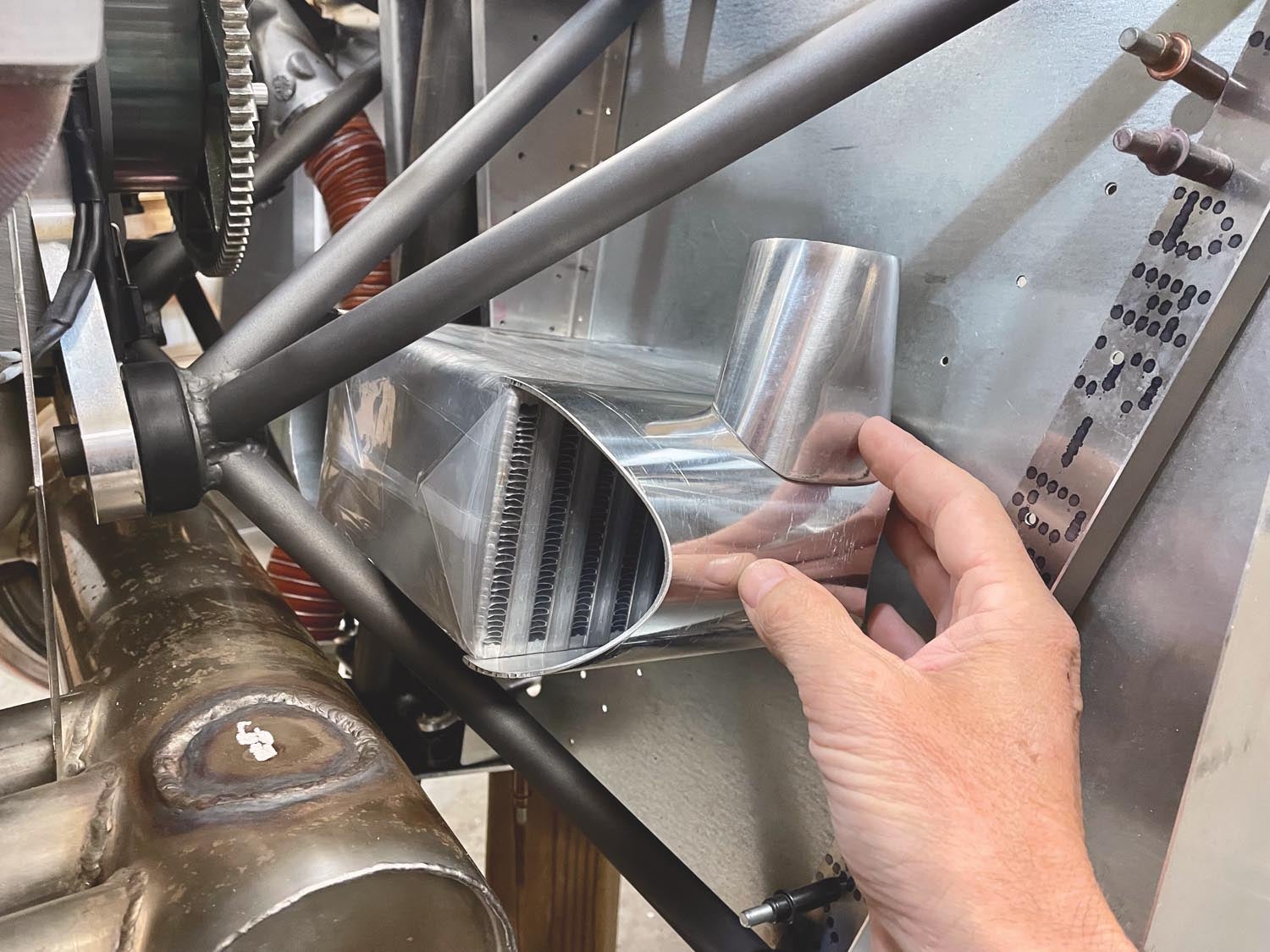
The best location I have found for the intercooler that meets most of these personal requirements is tucked down into the engine mount against the firewall. The cooling airflow will need to be directed straight down through the intercooler, hopefully exiting nicely with the rest of the air leaving the bottom-rear of the cowl. This position makes the engine intake piping a bit of a challenge because of the limited space and it will be slightly lengthened when compared to the first location I had considered. Along with that, I plan to build a carbon fiber duct/shroud from scratch that will tie into the scoop on the top of the cowl for forcing the air down through the intercooler system. I used a similar setup on the Super701 with the top scoop feeding down through a pipe. It has worked flawlessly and I hope the 750SDX will do the same. The intake piping and extra carbon fiber work will be custom components on the to-do list a little later on.
For this article, I really just intend to describe the sequence of events leading up to building a usable intercooler that can be mounted in the desired location. Since I was unable to find an off-the-shelf intercooler the size I wanted and with the appropriate intake and exit configurations, I was left with the option of either having one custom built or custom building one myself. Having an intercooler custom built requires you to have all the fittings, mounting points and end caps precisely figured out and drawn in a format that is easy for the fabricator to assemble accurately. This can be very tough to do when there are so many variables for mounting points, angles of pipes, interference with other components and other obstacles to figure out along the way.
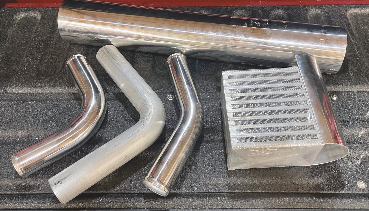
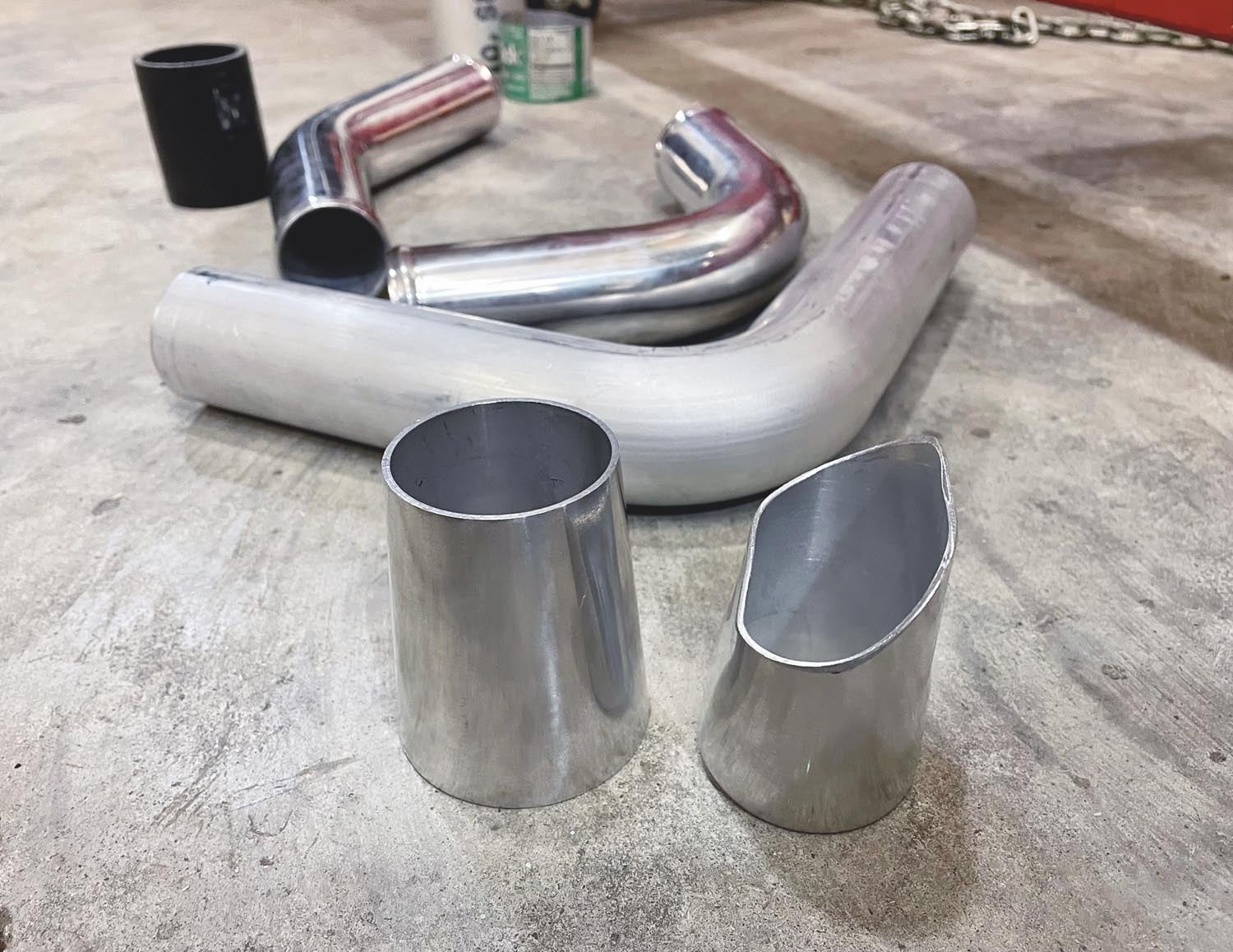
I finally decided to take on the challenge of custom building an intercooler myself. Once I decided on the specs and sizing, I had to order the Bell intercooler core and some aluminum tubing, transitions and other pieces in order to begin the fabrication process.
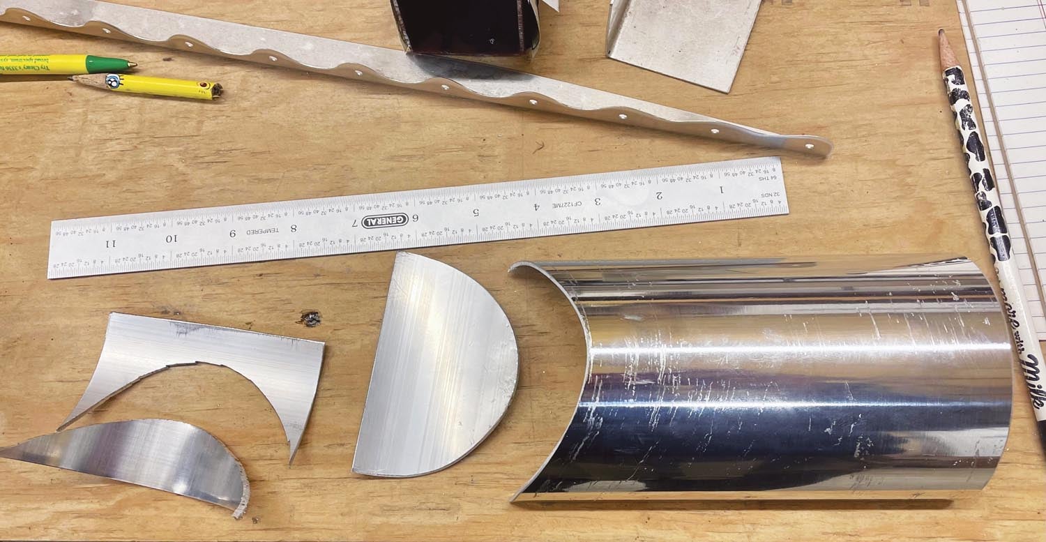
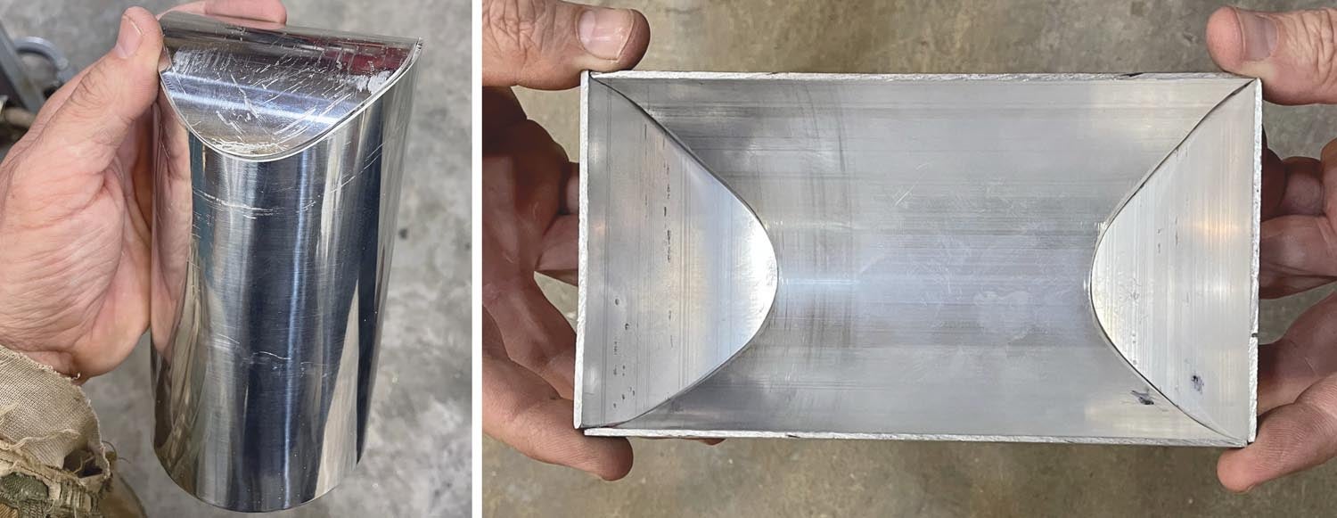
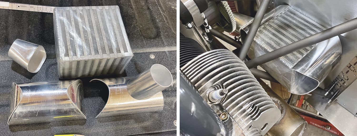
Most intercoolers have end cups with very square corners and ends, usually boxy and made from flat pieces with a round tube welded into it for the engine intake plumbing. I like to have smooth rounded edges where possible and decided to use aluminum tube to create these end cups. My intercooler core is 3.5 inches thick, so for the end cups, I am starting with a 4-inch aluminum pipe that is split down the middle and then lightly squeezed together to make the rounded ends. I am also using a piece of the 4-inch pipe to fabricate the outside ends of each rounded end cup. There are now a lot of curves to work with and fit up. Careful measuring, sketching, making templates and then cutting, sanding and bending all these pieces into the correct shape by hand is terribly time-consuming.
I started with the main body of the end cup, a piece of the 4-inch tubing cut to the correct width and bent to fit over the end of the intercooler core. Then the cup ends were cut to match the curve of the 4-inch tubing and traced into the end cup. After that, I went back to the saw to cut out the half-moon-shaped curves out of the end cup and trimmed everything to fit nicely. This is where the time consumption comes into play because you have to cut, test fit, cut, test fit, sand and test fit dozens and dozens of times to make all the edges nice and smooth for the TIG welding that will be required soon.
I also have to figure out how to orient and start the inlet/outlet pipes for the intake system to/from the intercooler. So, along with my order for intercooler parts, I also ordered a couple of tube transition pieces, a few 90s and a 45° tube bend for cutting and fabricating the intake piping system. Luckily, my half-tube round end cups fit the intercooler core tightly enough that I could slide them on the intercooler and position the entire assembly inside the engine mount so I could really study different ways and ideas to make it all come together (time for more head-scratching).
Once I had a basic idea in mind, it was time to start whittling out more pieces. It would be nice to do all this work with the latest CNC technology, but unfortunately most of the fabrication that happens on Humberd Farms follows a more hands-on approach, using hand saws, band saws, sanding belts, files and drills.
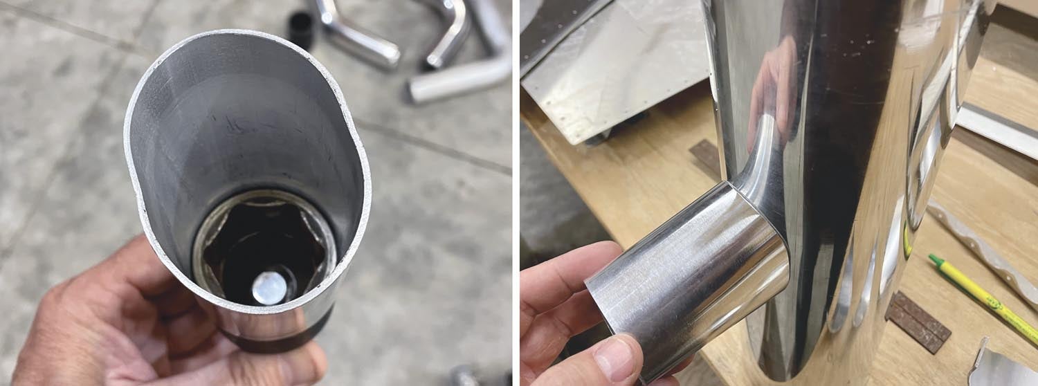
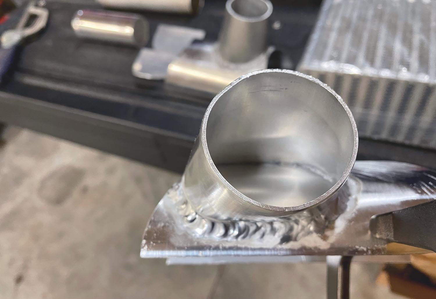
Now that there is a pile of usable intercooler parts on the workbench, it is time to turn the transition pieces into an idea I have to merge the intake tube with the intercooler end cups. I want as smooth of a merge as possible, so I took a couple of transitions and formed the larger end into an oval shape. This allows the intake air to slow down slightly and spread across the end of the intercooler core more evenly, or at least that is my reasoning. The basic forming for these was easy. I simply put a tight-fitting socket into the small end and then squeezed the large end in a vise until it became a useful oval. The socket keeps the small end shaped correctly to fit the standard round intake tubing for the upcoming TIG welding. Of course, coping and shaping all the curves by hand to fit each other is a lot of work, but it’s rewarding once you start to see everything actually come together.
Time To Weld!
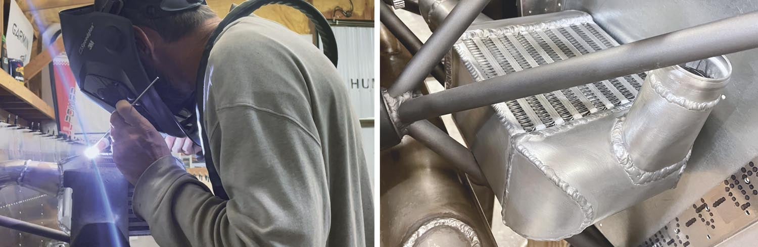
I have been TIG welding on and off for 30 years, but only have an aluminum project to weld up every three to five years. Since there is so much gap in between welding aluminum, I am not proficient at making aluminum welds look beautiful, but I am satisfied that I can make them structurally sound.
Many welding professionals won’t even touch aluminum because it is significantly different from welding chrome-moly, stainless steel and other steels. I could have the welding hired out, but at this point, I just want to be able to say that I did that part too. After digging some aluminum scraps out of the bin and wasting a few welding rods while practicing, I feel comfortable enough to have a go at welding the fresh intercooler pieces that I have spent so much time cutting and fitting up.
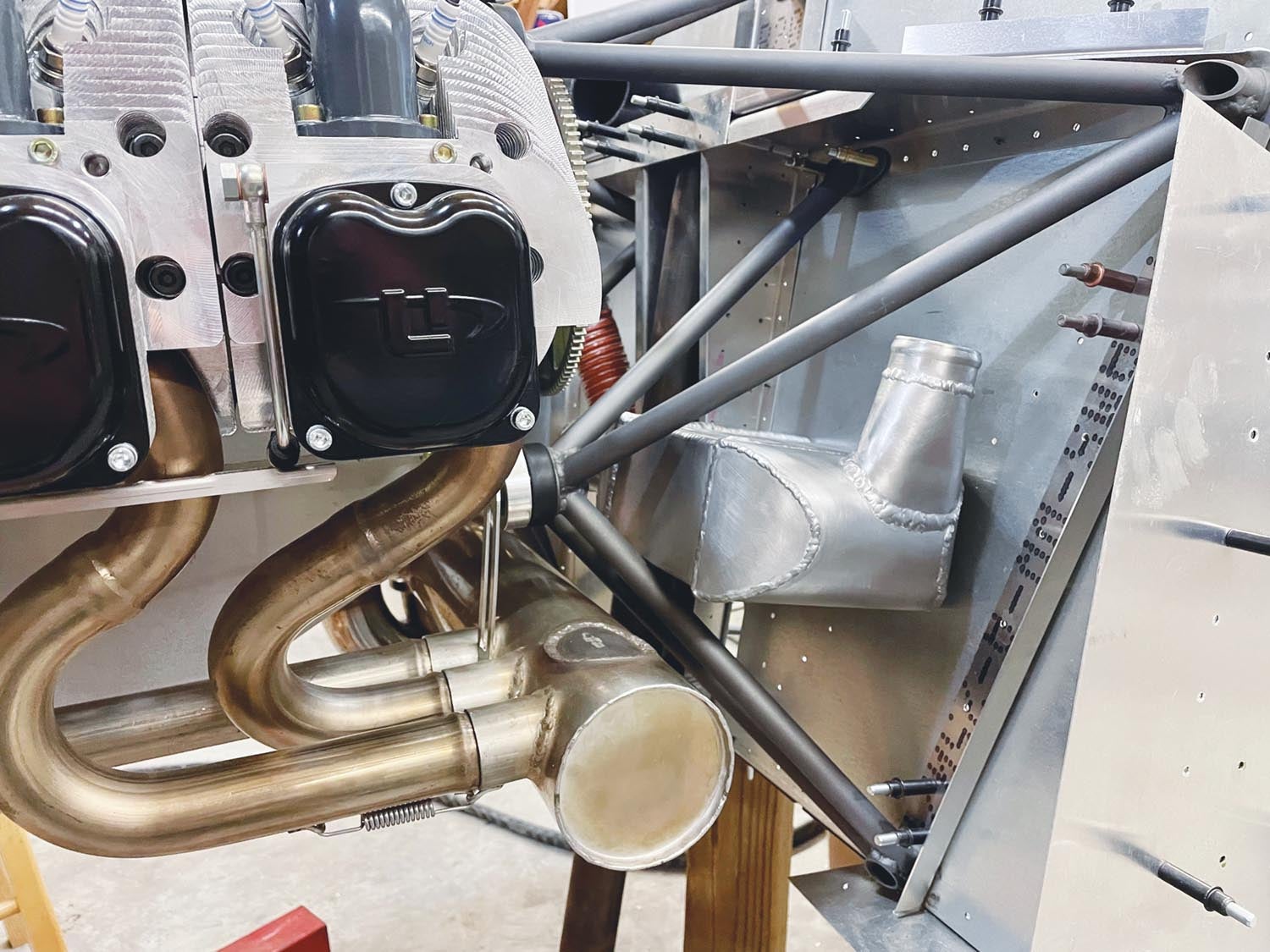
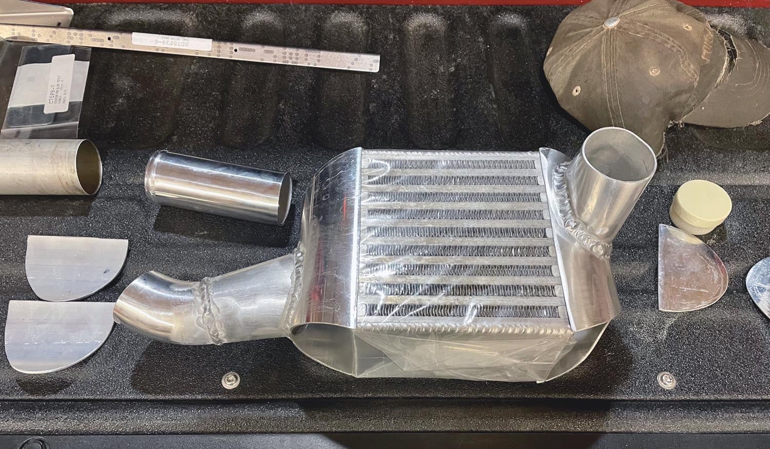
The order of the parts being welded is very important so you don’t back yourself into a corner. Welding the newly shaped transitions to the main rounded end cup pieces is first on the list. Once these were welded, the task of cutting and “port-matching” inside took up plenty more time with a file and sander, but I am happy with the results. Next up is welding the tube ends onto the transitions and then welding the assembled pieces to the intercooler core. With a little last-minute fitting, sanding and tweaking of the end cup ends, I am finally able to weld these last two curved pieces onto the intercooler. The finished product is definitely an unusual-looking piece and the welds aren’t absolutely perfect, but hopefully its functionality and performance will be above average. The only thing left with the actual intercooler is welding on the mounting points and I haven’t quite gotten all that sorted out yet.
I know the intercooler assembly may not seem like a lot of progress when looking at the whole 750SDX project, but it is one system that I have been thinking about for a long time and I am really glad that it is mostly finished so I can move on to other time-consuming modifications!


