I love working with aluminum. Having said that, fiberglass has its advantages, not the least of which is the invisibility of repairs. Sure, its sticky, slimy and can leave you scratching like a dog after an all-day possum hunt in the deep woods of southern Georgia, but for minimizing the “4aw-shucks” factor, its hard to beat.
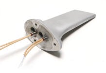
How much so is illustrated by my current project-building a Jabiru J250 LSA. [Expect to see a full series on this project later this year.-Ed. ] The kit maker says that the rear of the fuselage is molded around the horizontal stabilizer, so all I need to do is align it perpendicularly to the long axis of the fuselage, and then shift it laterally so that the same amount of stabilizer is on the left as is on the right. Seems simple enough…but whoa! Either this hangar is falling over or that horizontal stabilizer is, er, not quite horizontal.
The first thing to do is make sure that the fuselage is level, and the best place to check it is right across the wing supports. The manual advised that the bottom of the doorsills is the point for checking for level. However, in that I would prefer to have flying surfaces parallel to flying surfaces, it seemed silly to select the doorsills. After all, I like to fly wings level, not doorsills level.
As it turned out, though, my preferred reference agreed with theirs. A bit of scrounging and a long carpenters level allowed a confirmation of two things: 1. The fuselage is level. 2. The level is level. Digital levels are really fun, but they can be wrong. You must check them periodically for correct reading, and if they’re not telling true, recalibrate them. The instructions for doing so are not exactly simple, but its absolutely vital to do this or you’ll be wrong to several decimal places.
How to Fix It
With the wing attach points and door sills confirmed to be level-and therefore the horizontal stabilizer confirmed not to be-the procedure for correcting this had to be determined. The kit maker suggested that it simply be twisted to straight, temporarily locked down with sheetmetal screws and glassed in place. That brute-force approach didn’t appeal to me, nor did the potential of inducing residual loads. Thinking about it for a while, I suspected that when the system sat outside in the hot sun, the residual load would simply cause the tail to wind right back to out of alignment.
But a second realization presented itself: I might take advantage of those loads and the susceptibility to heat by twisting it past level, and then applying a heat gun. If I could support it in just the right position while it cooled, I might get it straight and with no stresses built in.
Carefully placed alignment marks were made, and then supports were positioned under the left end with weights on the right end. This induced a twist in the opposite direction, and, when it had gone past zero by 0.5, clamps and then sheetmetal screws were added to guarantee Id get back to this position.
Bondo might cover a few screws, but nothing was going to hide the C clamps, so epoxy/flox would have to be added between the joining surfaces. This required that all of the hardware be pulled off followed by a wipe down with acetone.
The stabilizer is removed by sliding it out sideways. Therefore, adding a coat of epoxy or flox would not be possible without smearing it down half the stabilizer. It was necessary to pry the gaps open enough to paint some straight epoxy on the mating surfaces, add some epoxy/flox, and screw it together. Put it on the supports, add the weights and check that its back to 0.5. Good.
The criticality of this procedure had me frequently confirming that the fuselage was still level. With all of it looking good, and with a silent prayer to the gods of fiberglass, I started carefully painting around the interfacing surfaces with a heat gun. Now, this isn’t your mothers hairdryer; this will take graffiti off a New York City subway station, so careful use is the order of the day. My technique was to heat the tail cone and its flanges while avoiding the stabilizer as much as possible. The last thing I needed was to turn the once-straight stabilizer into a Z shape. Doing it evenly, and not excessively, was controlled by placing my hand on the tail after applying a bit of heat. Bringing it up to a bit too hot to keep my hand on it seemed about right.
Now came the hard part: leaving it alone. I worried that the torque Id placed on it might be too much, and Id come back the next morning to find it twisted the other way. It worked, though. It was at 0.4 the other way when I first checked it the next morning. Knocking out the blocks and taking the weight off let it snap back to 0.0.
The finishing touch was not anticipated; the gaps between the fuselage flange and the stabilizer disappeared under the pressure of the straps and the heat gun! Just add the required fiberglass strips, and its done.
Air in the Wing, Not Under It
The next repair required the direct involvement of the manufacturer. The left wing showed what looked like a delamination in the upper surface. Unlike a tube-and-fabric aircraft, the wingskin carries a significant portion of the load, so an obvious defect like this is not something to ignore.
Now, this is not a panic situation, but its not one to just paint over either. A careful examination top and bottom on both wings showed a similar blemish on the lower surface of the right wing. After a bit more data gathering, it appeared that what we had was a defect in the mold that caused a dry spot. We probably could have ignored it but preferred not to.
It should be stressed at this point that this is not something to undertake without direct involvement from the manufacturer. It may belabor the obvious, but a misdiagnosis of the situation could lead to a solution that is not effective, so it is imperative that an expert evaluation be made to assure that this is the proper fix for your flaw.
But how to repair it? The concept was fairly simple: Put epoxy where it should be. Getting the epoxy below the surface without tearing up the whole wing was the problem. However, just as your doctor doesn’t have to saw off a piece of your arm to give you a medication, the fix could be injected. And thats what we decided to do. A visit to our local veterinarian supply store was necessary to obtain a syringe and a large-gauge needle. Fiberglass covered in a gelcoat, however, is a bit tougher than a horses hide, so another method was needed to get entry to the zone to be treated.
A very small drill bit was considered, but in that we were aiming for a mid-layer, sufficient depth-control made that a dicey proposition. But an awl, or in our case, a trammel-point, was just right for punching through the first layer while giving a feel for the cavity below.
At first we tried a single injection point. That was not terribly successful, as it was not possible to determine if we were spreading the epoxy laterally. A lot of holes would let us keep trying until we found the void. The extra holes had the additional benefit that they not only allowed air to escape, they also bled epoxy, showing that the entire area was being filled.
Frequent wiping to show the extent of coverage left us feeling pretty confident that wed really solved the problem. All that was needed now was to finish the area as part of the pre-paint operations.
Now before any of you aluminum builders get to smugly thinking that this sort of thing doesn’t happen to metal airplanes, Id like to point out that when I started my RV-6, I was cautioned that first-time builders usually built between 1.2 and 1.5 airplanes. The stuff to the right of the decimal place was in a pile in the corner. I was right on target, too.
But thats another saga.


I`ll like to get the Build Your Skills: Composites (Part 1 to 6 ) saga, as a new builder I find it very interesting.
Thanks
For now, it’s best to read this series in the PDF issues. It starts in the May 2007 Kitplanes: https://www.kitplanes.com/may-2007/