Flash yourself, Part 3.
The flasher we did over the last two months was a fun toy and can be used in a non-critical application. This month we are going to grow hair on the little feller. Caution: This sucker can kill you. Its not like a transistor radio-450 volts is nothing to play with if you don’t know what you are doing.
What do we know about flashtubes from the last couple of months? We know that the flash energy is measured in joule, calculated by the equation J = x C x V2 where J is the energy in joules, C is the capacitance in farads, and V is the voltage across the capacitor in volts. We have two ways of increasing the energy (and thus the brightness) of our flashtube, and they are to increase the value of the flash capacitor and/or to increase the voltage across that capacitor. If we note that the energy goes up as the voltage is squared, then increasing the voltage across the capacitor will get us far more brightness than simply increasing the capacitance. Or we can do a little of both. Let’s start with the modifications to the power supply.
In the original, because we wanted to limit the output voltage to 350 volts, we chose R1 (the input current limiting resistor) to be 10Ω. Now wed like to boop (a technical term) that voltage to 450 volts and the resistor R1 drops to 1Ω.
Now that we are pumping nearly 40 watts (13 volts at 3 amps) into our circuit, Q1 and Q2 get unmercifully hot unless we heat sink them. The heat sinks you see in the picture will do for a minute, but if I were to make this unit so that it operated for hours on end without stopping, I would find a large block of aluminum to bolt the transistors to. Caution: The tab for the bolt hole in this transistor is electrically connected to the transistor drain (top terminal on the schematic) and you don’t want to ground this pin. Use a transistor mounting kit, which consists of a hyperthin mica washer and a shoulder washer so that the metal transistor tab is thermally connected to the chassis but electrically isolated. Use thermal grease between the tab and the washer, and between the washer and the chassis. Thermal grease isn’t particularly poisonous, but if you get it on your hands or your clothes it is the devil to wash out.
Parts Is Parts
It would seem simple to buy a larger capacitor for C1, but its not. Back when radios glowed in the dark (i.e., vacuum tubes) you could find several hundred microfarad capacitors at 500 volts from dozens of sources. What with low voltage transistors and such taking center stage now, high-voltage capacitors are practically nonexistent, so we revert to tricks we used back in the days when we wanted to run kilovolt plate supplies on ham rigs: capacitors in series. Two equal value capacitors in series divide the capacitance by two but double the working voltage. In our case, two 470μf 250-volt capacitors (easy to come by) in series give us 235μf of capacitance at 500 volts.
So whats the final joule count? One half of 235 microfarads times 450 volts squared is 24 joules. The little 30-joule, 10,000 flashes tube we used last month isnt going to last long at that rate
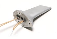
The answer is a larger tube, one that is also 30 joules, but is rated at 300,000 flashes at that power. And, as we said last month, if we run the energy down a little, and only flash once every 2 seconds or so, that tube will last nearly 300 hours of operation. We also found that letting the supply voltage dictate when the tube fired could be improved so that no matter what the supply voltage is, the tube will fire at a predetermined rate
The oscillator formed by U1A4 and U1A5 has a period determined by the values of C5, C6, R8 and R9. Ive chosen values so that R9 is set to midrange for a flash rate of once every 2 seconds. Note that we are using another trick wiThC5 and C6. These are polarized capacitors that expect the (+) positive end of the capacitor will always be more positive than the (-) negative end. In an oscillator, we cant guarantee this, but putting them tail to tail unpolarizes them.
What we want Q3 to do is pulse the trigger transformer for a few microseconds, just long enough to start the fire in the bottle. The combination of C4 and R7 sets the on time of Q3 to be about 5 microseconds, long enough to completely saturate the trigger transformer (T2). So the sequence is that U1A5 burps and ticks Q3, which raps T2, which gazaps I1, which gazooms C1/C3.
The table (see the PDF file) lists the changes for this months modifications (any non-critical parts like -watt resistors and low-voltage capacitors are not included; Jameco capacitors are less expensive).
Now no engineer in his right mind (oxymoron?) is ever satisfied with a design, and Im certainly not ready to sign this one off for production. Id probably look around to find a more efficient power transformer than one of these old filament transformers, Id experiment to find the exact frequency at which the transformer should be driven for best efficiency, and Id use driver FETs that had a lower on resistance to cut down on the heating, Id drive them with a D-type flip-flop to eliminate the both on for a few milliseconds phenomena and a few other minor enhancements. But for less than $35 in parts? Probably not. This is about as inexpensive as it gets.
Whither from here? Ive been promising you that I was going to get around to electrifying your hangar or workshop, and I probably ought to keep that promise. It will likely be a three-parter and probably not in three sequential months. When Im talking a few dozen amperes of 12-volt current, it will take me a good month just to wring out the design, much less write about it.


