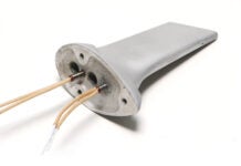
Before attempting to make full-sized composite parts from 3D-printed molds, the author gained experience by making a 3D model of the Sky-4 Cloud Trekker.
Background
Production of composite parts for light aircraft remains today a comparatively expensive process requiring many man-hours of skilled labor and one or more molds that are themselves expensive to produce. Given the low cost and high availability of 3D printing, it is possible, at least in theory, to create durable composite part molds rapidly, accurately, and affordably. The purpose of this article is to share what was learned from 3D printing molds for several different composite parts.
As part of developing the Sky-4 Cloud Trekker it was decided to produce four different composite fairings (see Figure 1). From smallest to largest, the fairings are: rudder bottom (4.1 x 6.1 x 2.7 inches), horizontal stabilizer tip (7.1 x 4.9 x 4.7inches), rudder tip (26.0 x 4.4 x 4.0 inches), and elevator tip (27.3 x 5.2 x 3.3 inches).
Building on previous experience gained by 3D printing desktop models and full-size parts for fit-checking and making tooling, the Sky-4 empennage fairings were an excellent opportunity to end up with some flightworthy parts, while at the same time developing a set of guidelines for designing future 3D-printed composite part molds.
Choosing the Printing Process and Supplier
Most home-use 3D printers lack both the resolution and print volume size necessary to make truly useful composite part tooling, but by using an on-line service such as Quickparts, Stratasys, or Shapeways, anyone can affordably make accurate, high-resolution parts up to 24 inches long.
All of the molds were made of nylon using the selective laser sintering (SLS) process. SLS was chosen mainly for affordability, but also because it offers the largest work envelope and resolution fine enough that details such as joggles and fastener locations could be incorporated into the molds. The nylon material was chosen because it is relatively strong and stiff, without being brittle. A finished SLS part, however, has a fine powdery surface texture which could make getting the cured part to release from the mold a bit of a challenge.
Price quotes were received from three online 3D printing services: Quickparts, Stratasys, and Shapeways. By far the most affordable of the three was Shapeways, and all molds mentioned in this article were made by them. Some printing services offer very short turnaround times, so if you are in a hurry to receive your 3D printed parts, another service may be a better match than Shapeways.
Goals
Beyond the obvious objective to end up with parts that could be used on a flying airplane, the goal was to find answers to the following questions:
• Given the powdery surface texture of an SLS part, would it be possible to remove the cured part from the mold? Once removed, would the resulting part require so much more time to fill, smooth, and prep the surface for paint that there is no advantage to a 3D printed mold?
• Is the SLS process sufficiently accurate to produce molds having not only joggles where the fairing underlaps the sheet metal skin, but also fastener holes with dimples for flush-head fasteners molded-in?
• Is the SLS-printed nylon sufficiently strong to tolerate whatever amount of pulling, prying, and peeling is required to get the cured part out of the mold?
• Is SLS nylon dimensionally stable enough over a long period of time to allow a large number of “production” parts to be produced?
• What is the best approach to designing a 3D printed mold that is both durable and affordable?
Rudder Bottom Fairing
Being the smallest of the four fairings, the rudder bottom fairing was chosen as the first part for which to print a mold.
The mold was designed in two symmetrical halves that would be held together with -inch bolts. The intent was that the mold halves are bolted together while the part is being layed up and cured, then separated when it is time to remove the part (see Figure 2).

Figure 2: The rudder bottom mold consists of two symmetrical halves that are held together with 1/4-inch bolts.
The rudder bottom fairing mold was designed with a minimum thickness of .394 inch. The mold extends a half inch past the actual edge of the part. This allows the part to be laid up deliberately oversized, then trimmed cleanly back to “net” after it has been removed from the mold.
The complete mold set cost $323.18. The actual molding surface area for this part is 56.0 square inches, which means that the cost per unit area of the actual mold surface works out to $5.77 per square inch.
In order to make it as easy as possible to remove the cured part, the mold was liberally waxed, then brush coated with PVA parting agent before laying-up. The part was made from 8.8 ounce-per-square-yard 7781 E-glass fabric and West System room-temperature-cure epoxy. Fortunately, the part came off the mold without damage to either the part itself or the mold. The amount of effort required to remove the part was, in fact, not significantly different than what would have been needed to remove a part from a polished surface mold. A total of three rudder bottoms were produced with no perceptible wear or damage to the mold (see Figure 3).
The rudder bottom mold turned out to be more than strong enough to tolerate the stress of removing the part. The matching holes in the mold halves were a tight fit for the long bolts and they required a fair amount of effort to insert and remove. The two mold halves fit together so well that there was no gap large enough for a tool to be inserted to gently pry them apart. Although expensive, this first-generation 3D-printed mold set turned out well, but areas of improvement for future molds are already becoming apparent. Let’s move on to the next part and see if it can’t be done better!
Horizontal Stabilizer Tip Fairing
The next largest of the four fairings, the horizontal stabilizer tip, is different from the rudder bottom in that it has an acute-angle closeout on the back side, making it a more technically challenging part (see Figure 4).

Figure 4: The horizontal stabilizer tip has an acute-angle closeout on the backside, making it a technically challenging part.
The minimum thickness for this second-generation mold was .157 inches—less than half as thick as the rudder bottom mold—but with a .375-inch-thick spine where each mold half mates and .157-inch-thick stiffening flanges. This and all subsequent molds also extend a half inch beyond net, so as to allow for final trimming of the part after it is removed from the mold. Hopefully this thinner mold will be strong, stiff, and stable enough to produce useable “production” parts.

Figure 5: An offset in the mating surface of each mold half produces slots into which a thin tool can be inserted to help pry the mold halves apart.
Another new design feature is the addition of an offset in the mating surface of each mold half, at each of the three corners of each mold half. This produces slots into which a thin tool (think screwdriver blade) can be inserted to help pry the mold halves apart (see Figure 5).
As before, the mold was waxed and coated with parting agent before beginning the layup. None of the parts mentioned in this story were bagged, and the layups were mostly straightforward. The one place where it was a challenge to get the uncured plies to conform to the mold was in the acute angle between the concave aft surface and the convex forward surfaces of this part (see Figure 4). Once the first mold half was popped free, the cured part was easy to remove from the second mold half. The pry slots were effective and the 3D printed plastic was able to tolerate gentle prying without significant damage or wear. A total of six parts were produced and, while only time will tell, it appears that the mold will last indefinitely.

Figure 6: The horizontal stabilizer tip mold was used to produce these six parts. It appears that the mold will last indefinitely.
The complete mold set cost $304.16. The actual molding surface area for this part is 98.7 square inches. This works out to $3.08 per square inch of mold area. Being thinner means that less 3D printed material was required to make the horizontal stabilizer tip mold, which reduced the dollars-per-square-inch cost of to just over half that of the rudder bottom mold.
The biggest takeaway from the experience of making the rudder bottom and horizontal stabilizer tip is that making molds directly from a digitally defined CAD model allows the designer to incorporate features in composite parts that would have been impossible or, at best, significantly challenging if using the traditional plug-mold-part process. This is because using the traditional process, a plug with joggles, dimples or undercuts would be locked into the mold. (Plugs and parts are usually designed so that they do not get locked into the mold and release freely; this is called negative draft (see “Basic Mold Making” by Bob Hadley in the December 2015 issue of KITPLANES). Because 3D printed molds need no plug and can be designed to split apart, issues of draft can sometimes be overcome. Figure 7 shows how draft angle varies on the horizontal stabilizer tip mold.

Figure 7: Draft angles on the horizontal stabilizer tip mold. Yellow is vertical, green is positive, and red is negative.
The horizontal stabilizer tip fairing molds were a definite success, but the question remains: How thin is too thin? Since the price of a 3D printed object is based almost entirely on volume and not the complexity of the shape, it pays to make the mold as thin as possible and use lots of stiffening flanges and spines to ensure strength, stiffness, and stability. The horizontal stabilizer tip mold turned-out to be more than strong enough and stiff enough.
The results with the rudder bottom and horizontal stabilizer tip were hugely encouraging and have showed that spending the money to print molds for the rudder tip and elevator tip will be a worthwhile investment. Next time I’ll explain how I approached designing those molds, using the lessons learned so far.

![]()
Ken Krueger is an aerospace engineer, pilot, aircraft owner, and homebuilder, having completed an RV-6 and a single-seat aircraft of his own design. Ken’s company, Sky Designs Engineering (www.skydesigns.aero), specializes in light aircraft design.


