One of the curses of modern CAD technology is that designers can draw something up, then have the computer dimension it for them on the drawing – very, very precisely. In the case of the drawings I am using on my current project, the drawings tend to dimension to the nearest 1/64th of an inch if you find a line of rivets that has essentially been evenly spaced between two end points, you’ll find it a bit tedious to measure each hole’s location in 64ths of an inch from an end point.
But once you realize that they are literally even spaced between the end points, you no longer have to measure off each one – if you happen to have a rivet fan!
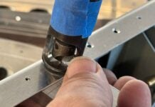
The rivet fan is a wonderful little device that you open and close to fit whatever spacing is required, and it gives you even hole spacing between each arm of the fan. So now all you have to do is to measure the two end points, and drill them with a #40 drill. Then count on the drawing how many total rivets you need in the line, cleco the end of the fan to one end of the line, count off that many arms, and cleco the appropriate arm to the other end hole. Now you can either mark every hole in between or, if you’re lazy like I can be, simply drill through the hole on the end of each arm! You now have an evenly spaced set of holes, and you didn’t have to measure off 4 – 49/64″, followed by 5 – 49/64″, followed by 6 – 53/64″. Yes, you might not have EXACTLY the spacing shown by the original drawing, but I bet it is closer than if you measure it by hand and a 64ths rule….. (Just make sure that if there IS a difference in spacing, you understand why, and if it is significant, like offsetting two opposing rivets like on the drawing shown here. In that case, space things from the second hole up!)


