A wide variety of modifications on the market claim to improve the performance of airplanes. In addition, homebuilders are continuously looking for ways to make their creations faster and more efficient. A large number of these modifications seek to reduce drag by improving the aerodynamics of some portion of the airframe.
Hard data on how well various modifications perform is difficult to come by. Manufacturers make claims, and some user testimonials exist, but well-documented before-and-after flight test information is scarce. We can infer something by looking at the evolution of the airplanes that win efficiency contests, and which after-market modifications remain popular for certified airplanes.
This month, we will take a quick look at some common types of modifications, and look at the aerodynamic effects they are intended to have. It’s important to note that how effective modifications will be depends on how well the original airplane configuration works. All speed mods are designed to improve the aerodynamics of some part of the airplane. If that area has issues on the original airplane, the mod may work very well. If the original airplane’s aerodynamics are good, the modification may have little effect. We can get some idea of how well a modification might work by understanding the aerodynamic issue it is designed to fix.
Gap Seals
We discussed the issue of gaps in the May 2013 KITPLANES®. Gap seals are designed to prevent air from flowing through the gap between a moveable control surface or flap and the fixed portion of the wing to which it is attached. If the gap is open, air will tend to flow through the gap, from the high-pressure side of the wing to the low-pressure side. This flow through the gap has two potentially detrimental effects: It generates drag, and it reduces the control power of the moveable surface, if it is a control surface. Flap gaps are somewhat different because some flaps are designed to have a slot between the flap and the wing to direct high energy air over the flap when the flap is deflected. In this case, the goal is to have the flap sealed to the wing when it is retracted, but have the slot open properly when the flap is deployed.
Aileron and elevator gap seals seek to seal the gap at all times. Good flap-gap seals must seal the gap only when the flap is retracted.
The positive effects of gap seals will be relatively small, unless the original gaps are large. Aileron gap seals will most likely produce their largest improvements in climb and slow cruise. They will also improve aileron control in slow flight.
A flap-gap seal that seals the relatively large gap on the lower surface of a stowed, slotted flap will have more effect in cruise. A potential drawback of flap-gap seals is that they alter the geometry of the slot between a deflected flap and the wing and may reduce the effectiveness of the flap. Accordingly, the gap seal may improve cruise performance, but hurt stall speed slightly.
Wingtips
Wingtips are one area where many geometries have been tried, and some rather dramatic claims have been made from time to time. The shape of the wingtip affects how the air sheds off the end of the wing and forms the trailing tip vortex. A good tip design causes the vortex to roll up as far outboard as possible and as weakly as possible.
Tips that curl out of plane with the wing either up or down are seeking to fence the tip flow to reduce the strength of the vortex. Tips with sharp outer edges are trying to fix the point where the vortex sheds to the outermost extent of the wing to maximize effective wingspan.
Because they affect the tip vortex, and the effective span of the wing, wingtips primarily affect the induced drag of the airplane. Induced drag is most significant in climb and relatively slow flight. Accordingly, an effective wingtip improvement is most likely to give a measurable improvement in rate of climb, and may also show some improvement in slower economy cruise flight. Be suspicious of wingtips that are claimed to produce large top speed improvements.
Cowlings and Cooling
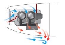
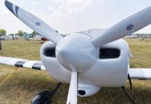
Cooling drag can account for as much as 15% of the total drag of a well-designed airplane. An inefficient cooling system can generate even more drag. Because of this, improvement in cooling flow is one area where significant gains in cruise performance are possible.
The key to an efficient cooling system is to take as little air as possible onboard, use it efficiently to cool the engine, and then return it to the outside air flowing aft with as much velocity as possible. To do this, we need small, efficient inlets feeding an internal arrangement in the cowl that confines the high-pressure air taken onboard with a minimum of leakage and directs it through the cylinders. We also need an exit that smoothly directs the air aft as it leaves the airplane after flowing through the cylinders.
The cooling systems on many airplanes lack one or more of these features. They are often designed to generate more airflow over the engine than necessary in order to ensure robust cooling over a wide range of conditions. Baffling is often designed with cost and ease of production, rather than efficiency as the primary concern. Finally, the cooling air exits on many airplanes are relatively primitive, and once again designed with ease of production and reliable cooling in mind.
Improvements in any or all of these areas can produce quite significant reductions in drag. One caution: Keeping the engine cool is critical to safety of flight. Keep good cooling of the engine in mind when attempting to reduce cooling drag. A low-drag cowl that causes the engine to overheat is not an improvement to the airplane.
Landing Gear Fairings
If it has no fairings at all, a typical tricycle landing gear for a light airplane can account for as much as one-third of the airplane’s entire parasite drag. A good set of landing gear leg and wheel fairings can reduce the drag of a fixed landing gear by about 80%.
Most fixed-gear airplanes have some kind of fairings on at least part of the landing gear. Improving the effectiveness of these can have a significant effect on cruise performance.

Fairings on the wheel itself reduce drag considerably, but note that in the photo above, the gear leg itself isn’t faired. Both the leg and the wheel are faired in the second example, below.
A typical gear has several components exposed to the wind. The most important of these are the leg, the wheel, and the brake assembly on the maingear. Properly fairing all of these minimizes the drag of the gear.
On many production tricycle-gear airplanes, it is common to see fairings over the maingear legs, and wheel fairings on all three wheels. Often, the brake assemblies on the maingear and the strut of the nosegear are exposed to the air.
Tight-fitting wheelpants that minimize the frontal area of the fairing and fit tightly to minimize the drag caused by air flowing into the fairing around the wheel can yield a small drag reduction compared to production wheel fairings. One company offers wheelpants with bomb bay doors that close around the wheel, sealing the fairing entirely. Adding a fairing around the brake assemblies gains a little more.
The big chance for improving landing-gear fairings lies in fairing the legs. A cylinder in crossflow has very high drag. It is common for the leg of a landing gear to generate more drag than the wheel it supports, even if the wheel has no fairing. It is quite common for production airplanes with oleo-strut nosegears to have the strut exposed directly to the airflow. This situation is exacerbated by the fact that the nosegear strut is directly in the propwash.
Several types of fairings are available to address this problem. They include trouser fairings attached to the nosewheel fairing that enclose part of the strut, similar fairings extending down from the fuselage, and fairings that attach directly to the strut.
The drag of the landing gear is parasite drag. Accordingly, drag reductions from gear fairings will have their greatest favorable effect in cruise and high-speed flight.
Wingroot Fairings and Seals
A final area of concern is the junction between the wing and the fuselage. As the air flows over this junction, the wing tries to direct the flow one way; and the fuselage, if it is not properly shaped, tries to direct the flow in another. The result can be flow separation, premature stall, and a significant drag increase, particularly in climb and economy cruise. Allowing any air to flow through a gap between the fuselage and wingroot can also have large, deleterious effects on drag, particularly in climb.
Properly fairing the wing to the fuselage with fillets, and sealing the joint between the wingroot and the fuselage if it is open, can help.
The effect of wingroot junction fairings is one of the most configuration-dependent phenomena in the quest for aerodynamic improvement. If the original fuselage is properly shaped, and the root junction is well sealed, adding fillets will have no beneficial effect, and may actually increase drag slightly. On the other hand, if there is significant flow separation near the root of the wing, some relatively simple fairings can provide a significant improvement.
Fortunately, unlike some other areas we have discussed, it is relatively easy to visualize the flow over the wingroot and fuselage side using either tufts or oil to see if there is significant separated flow that could be re-attached with proper fairings and seals.

![]()
Barnaby Wainfan is a principal aerodynamics engineer for Northrop Grumman’s Advanced Design organization. A private pilot with single engine and glider ratings, Barnaby has been involved in the design of unconventional airplanes including canards, joined wings, flying wings and some too strange to fall into any known category.


