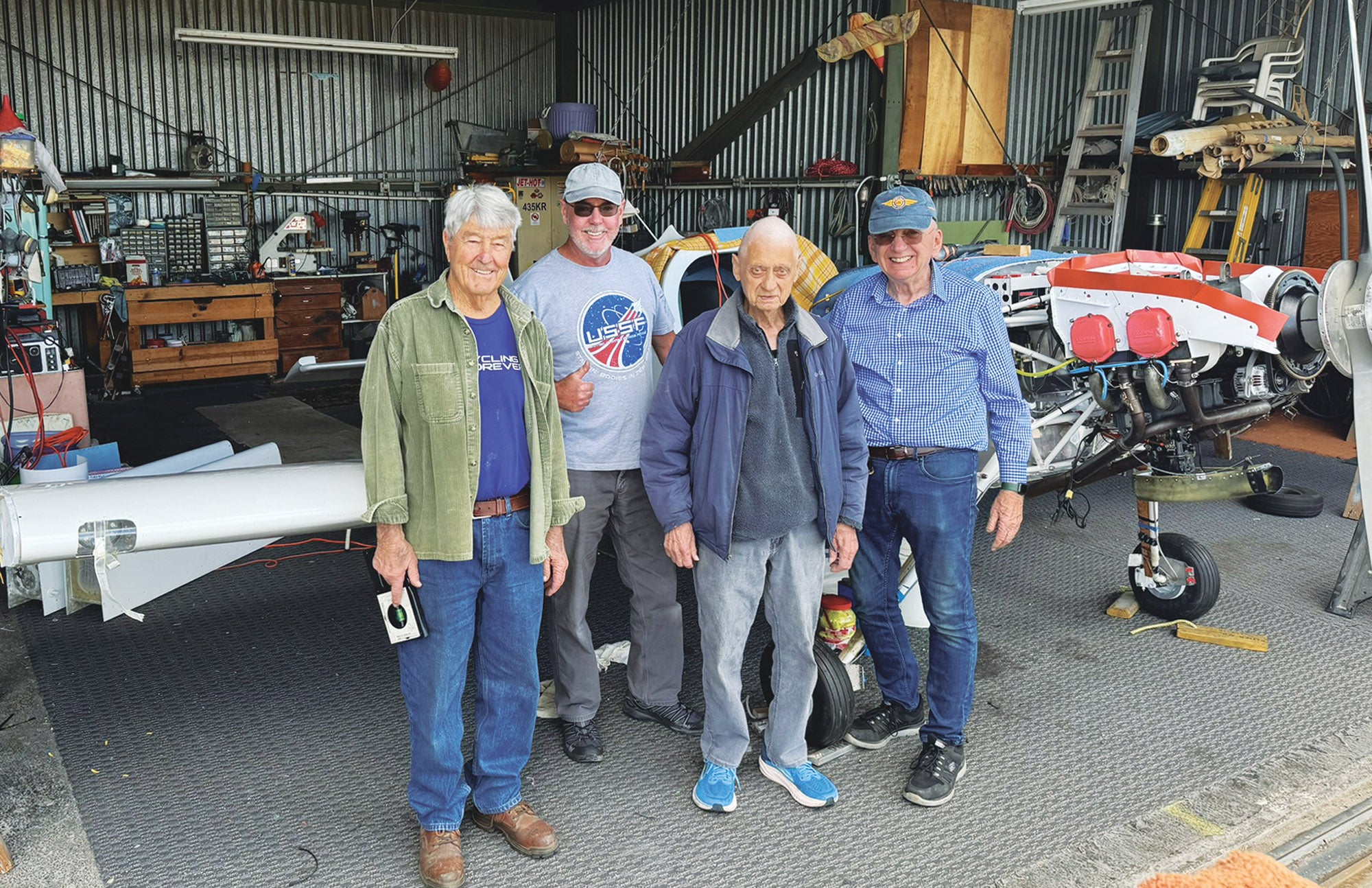
How many airport friends does it take to reattach the wings to a Van’s RV-6? Realistically, probably three. However, here at Sacramento Executive Airport (KSAC), word tends to spread like wildfire and before you know it, the whole squad is there to help. This includes “the boys.” Stan Lawrence, Bruce Walters, Kerry Richburg and (the late) Hal Pattenaude plus Zach Lauzon, my boyfriend. In early summer of 2024, the six of us managed to get the wings mounted and bolted on in only 3 hours.
When we first removed the wings, Stan had created handles to attach to the outside wing rib for easier maneuvering. These were still attached so he and Bruce were able to easily pick up each wing from the wing stands and slide them into their respective slots in the fuselage. The main spars of the wings are attached to the structure with more than 50 fasteners, mostly bolts. That’s not just the spar-to-fuselage joint; these fasteners also clamp the pieces of the spar together. Of course 16 of those are “close tolerance bolts” and are very tricky to get in. Stan carefully lined up the spars with the mating holes in the spar bulkhead with the larger bolts and started pressing them through. Afterward, Zach and I (and our youthful knees) took over and finished attaching each bolt one by one. Stan leaned over the edge and supervised.
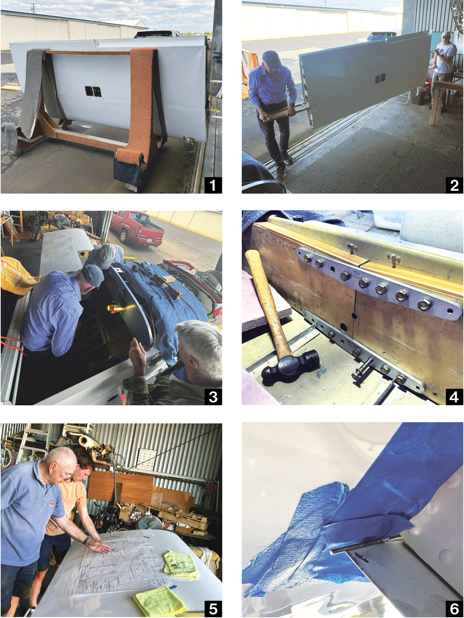
The rear spar of the wing is attached with only one bolt. When building a Van’s RV-6, correctly drilling the rear hole for this bolt is a crucial step as it establishes the angle of incidence for the wing. Thankfully, we didn’t have any drilling to do! While Zach wiggled the wing, Stan slid the bolt through and finished tightening it and we were good to go!
After removing the fuel tanks, which had been loosely screwed into the wings for safekeeping, Kerry, Hal and Zach organized the hangar a bit. Without the wings taking up space in the corner, we now had more space to work with!
The flaps on a Van’s RV-6 are attached via a piano hinge and two long wires feeding through it. Reattaching the flaps proved to be difficult. Using needle-nose pliers and safety-wire pliers, we were able to push the wire most of the way through the hinge. But the last 4 inches kept getting stuck! After some trial and error, we got it! We figured out a pro tip: If you don’t want to scratch the paint on your plane, just tape it off with blue tape! Just be careful when you pull the blue tape off. If you aren’t careful, it is easy to accidentally pull the paint with it. But overall, it worked like a charm.
Once we managed to get the flaps on, things didn’t seem to be lining up. Why? Then we remembered. These weren’t the original flaps! These were the ones I had brought from Colorado and they came here on a PC-12! So, we needed to realign the piano hinges. The flap motor worked well, but the arm attachments for the flaps would rub against the bottom of the fuselage because the hinges were mounted slightly differently on these new ones. We just needed to replace the hinge on the flap to match the one mounted on the wing. My friend from New Zealand, Dom Barry, came to help. We moved the piano hinge over by about half an inch and Stan reinstalled the hinge to be in the correct spot. After moving the piano hinge over and widening the space in the fuselage where the flaps were rubbing, they could finally go up and down with no issues! So a note to fellow restorers: Early kitbuilt airplanes like the RV-6 can be safely assembled in many ways, with so many little variations, that there’s no guarantee parts from one will fit (and work properly) on another.
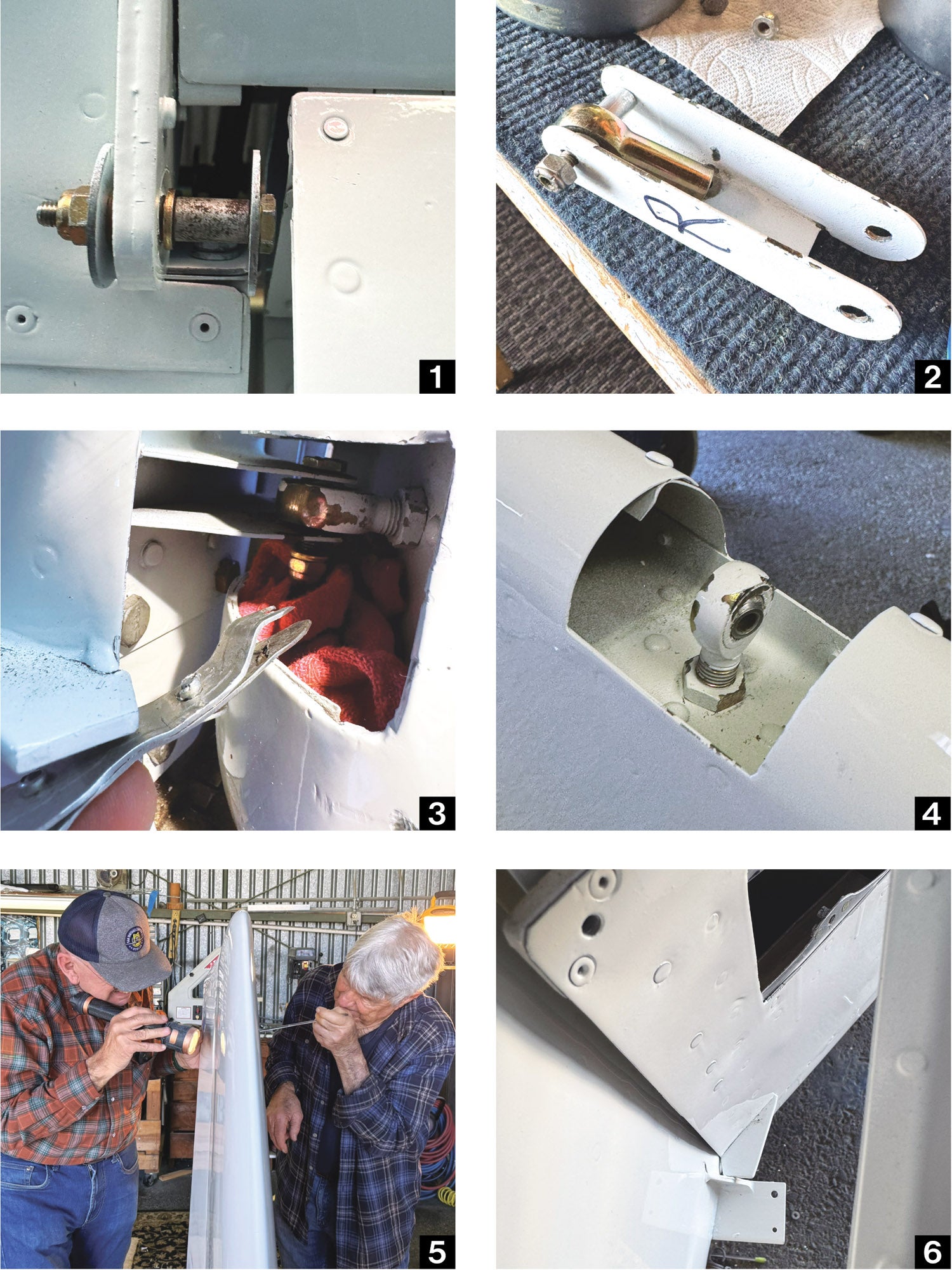
After successfully attaching the wings and flaps, it was time for the ailerons. Installing these was not a breeze either. Cheers to another project to troubleshoot! From the beginning, the ailerons, when in full trailing-edge-up deflection, rubbed against the wings. We could tell because the paint had worn off the tops and there were black streaks. This time, we wanted to fix them so they wouldn’t rub. We started by opening a gap at the upper wing skin, which created a slightly bigger gap for the aileron to freely move.
However, it didn’t make a big enough gap. It looked like the aileron pivot points—remember the RV-6 aileron pivots below the wing on brackets, it’s not a piano hinge situation—needed to be moved down away from the top of the wing. Upon investigation, we found out we weren’t the first to discover this problem and attempt a fix. Someone had actually elongated the holes in the aileron attach brackets to do this very thing! Well, that’s not going to fly.
We hoped to simply replace the attachments and drill them ourselves, so Stan and I bought a couple and Kerry and Zach decided to tackle the project. They started by connecting the aileron attachment rods on both wings. Then, they proceeded to work on the hinge attachments. Zach explained, “Taking a new attachment, we marked the middle point of the already drilled one and used a machine with a metal cutting bit to drill our hole.” Without a great way to measure exactly where to drill the hole, they eyed it based off of the middle of the larger hole that had been drilled previously. “We only had one shot at doing it. And we eyed it,” Zach added. Once Kerry and Zach had made a nice new hole that wasn’t elongated, Stan and I tried to get it to work. Unfortunately, it still didn’t. So, my friend Kyle Rodrigues is likely going to make custom ones! We will be continuing the aileron attachment project as soon as he is done.
On to the Rudder
The original rudder had cracks, so we replaced it with a new one. Once installed, the rudder wasn’t going quite all the way to the stops. It always came up slightly short. Thinking maybe the original end caps were too thick, we debated sanding down the fiberglass on the end caps. But before ruining the paint, we decided to try adjusting the cables, which was the cure. Once again, there are so many little airplane-to-airplane differences that changing flight controls will almost certainly require some rerigging. Just get used to it.
Then, we finished attaching the rudder to the vertical stabilizer with small bolts, washers and nuts. To paint a picture…Kerry (with his toothpick in his mouth) and Stan (with his phone in his chest pocket and flashlight in hand) and I took turns trying to drop the bolts into their respective places while the others held the rudder in place. Kerry made a neat tool to help guide the bolt in. We kept dropping the bolts and nuts while attaching the rudder, so instead of having to continue fishing them out with a magnet, we stuffed a towel underneath to catch falling objects. Finally, we managed to attach and tighten each bolt. Success!
Control Sticks Arrive
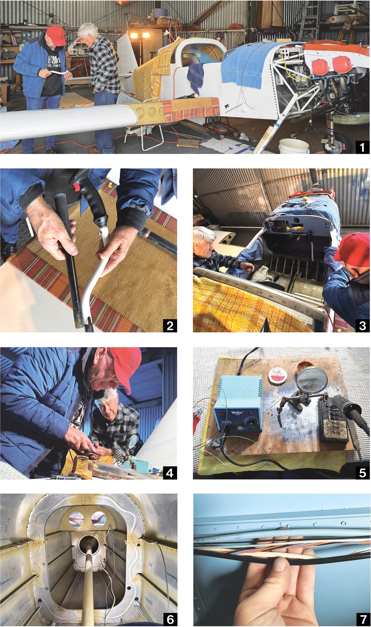
The original control sticks on N2165U were pretty basic and worn out. After spending many hours flying Stan’s RV-14 with the fancy RV-14/14A Right Control Stick with Tosten Grips, I chose to get some of my own because I’m bougie like that. Also, they are super comfortable and easy to use. They come prewired, which ideally will make installation fairly easy. However, these grips are a little long, as I sit pretty close to the panel (short people problems) and the panel is extended slightly lower than usual. After analyzing the way the new one was fitting in the plane, Stan, Kerry and I concluded it would be way too long for me. Fortunately, Kyle is going to make me a custom stick to go with the grip. I ordered one control stick from the Van’s website to test it out and see how it fit and still need to order the other. Will update more when we install them!
Learning To Solder, Running Wires Forward
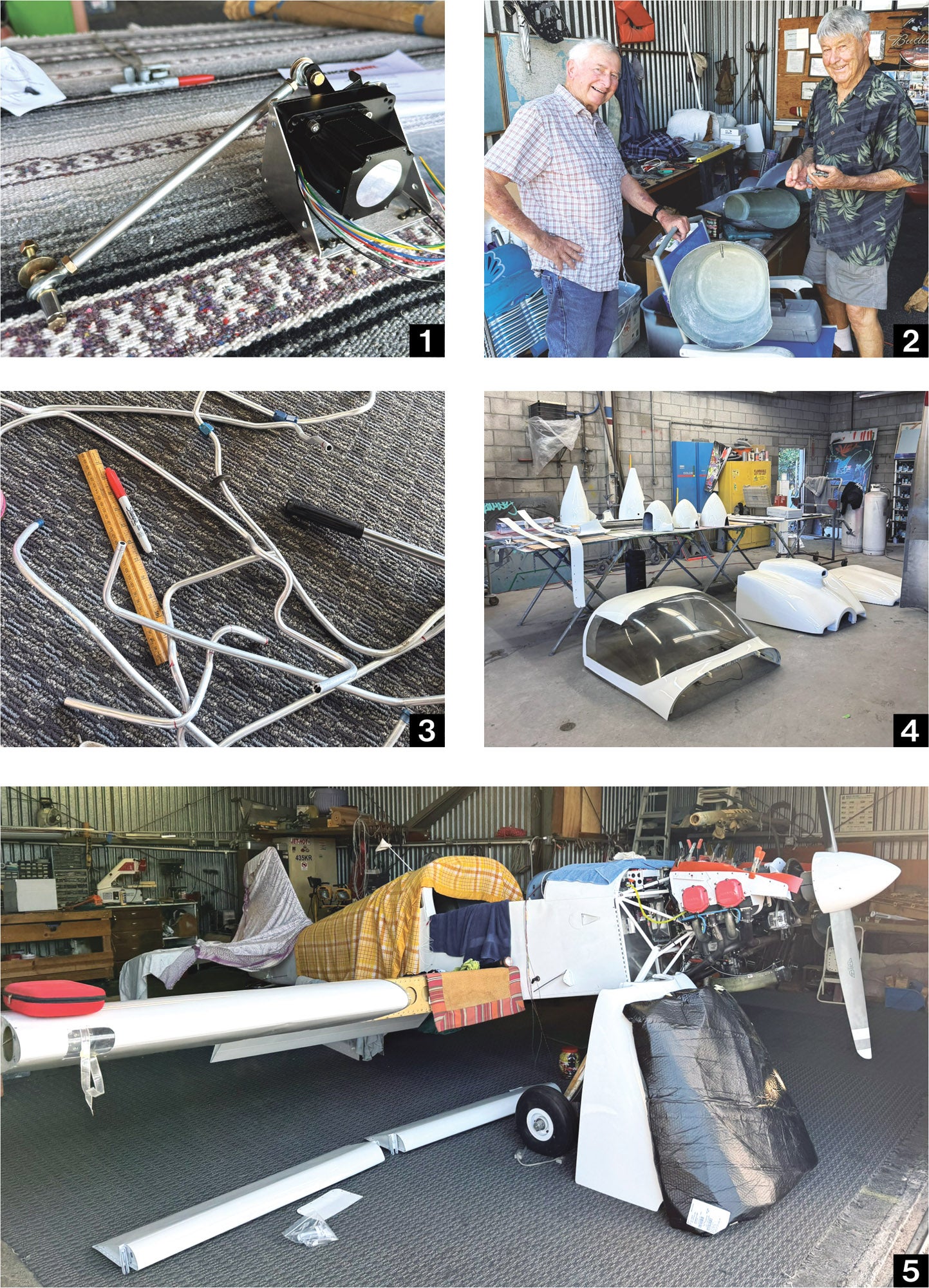
N2165U originally had manual trim, but I decided to upgrade to electric. Fortunately, we were able to reuse the holes from the original manual cable to run the wires for the electric trim.
The small-gauge wires from my new electric elevator trim motor wires came with a Molex-type connector. However, we chose to eliminate the connectors and solder instead as it would be easier to get them through the tiny opening between the elevator and horizontal stabilizer.
Stan and Kerry taught me to solder using an older Weller WESS1 adjustable-temperature soldering station. Stan emphasized that we must keep the wire hot enough so it would absorb the melted solder. He had to scrape and clean the tip of the soldering iron so it would transfer heat once we put the tip against the wire. Stan twisted together the ends of the wires we were attaching and bent them, then slid a little bit of heat shrink over the top to insulate them.
After soldering the trim wires, we needed to run multiple cables from the back to the front of the plane. Using a normal drill and widening with a pneumatic drill with the super-wide conehead end, we drilled small holes in each of the fuselage support ribs to get the cables through. After widening the holes, we slid snap bushings through. The next challenge was to fit all of the wires through the snap bushings. The wires that needed to go to the front included both ELT cables (flat white and thick black), elevator trim wires (small white and black), Dynon GPS 220 (orange, purple and black) and static air (clear-ish line with chipped blue paint, call it patina). After a lot of wiggling and patience, we finally got them to where we needed them.
Odds and Ends
I finally ordered my autopilot servos and received them in the mail! I waited to order them because I needed to save up. Once I placed the order, Advanced Flight Systems shipped them to me and I had them in two days. In the box, I got the mounting kit with instructions, the long output arm servo and bracket kit, and the standard output arm servo and bracket kit. After riveting nut plates to the bracket, we puzzled the backing plate to it and screwed it on. From there, we figured out how to attach the servo to the other side with four long bolts. The arm attaches the servo to the aileron with two bolts, spacers and long washers, similar to how we had mounted the aileron earlier.
After lots of trial and error, I finally finished cutting and bending my last fuel line to run the fuel from the right wing to the fuel selector. I messed up so many times that I had to order new tubing! I was trying to be a perfectionist with it but was ready to settle for what I had when Bruce stopped by. He encouraged me and reminded me to always strive for my best workmanship. He showed me a piece he kept from his RV-7 project that he had redone 10 times before getting correct—he had kept each piece he made as a reminder to himself to not give up! Also, Kerry noticed my multiple attempts and left me a note with a tidbit of advice to try bending copper wires first to use as a template, then match them with my more expensive tubing. I’m so thankful for both of them!
Picking up the Last of the Control Surfaces With Zach
Justin Frei, Gabriel Lopez and the rest of the amazing team at Ultimate Collision Center finished painting the last of my airplane parts! Thanks to my parents’ 1996 Toyota Land Cruiser and Zach and Gabe’s help, we were able to fit all of them in the car in one try. These parts included the canopy, cowling, wheel fairings, gear leg fairings, transition fairings and inspection plates. Like all of the parts from before, these all looked amazing! Thank you again, Justin and team!


