 I’ve learned a lot since my first flight lesson in October 2020. When I showed up at the airport, I didn’t know which direction a screw turns, a nosewheel versus a tailwheel or the functional differences between high-wing and low-wing aircraft—I am exaggerating but not by a lot. So honestly, I’m pretty proud that I can now sometimes grab the correct socket out of the drawer on the first try.
Despite feeling confident in some aspects, we all have our weaknesses. My biggest one is systems, specifically the electrical system. So, when it comes to wiring my own plane, saying it’s been a struggle to comprehend this stuff would be an understatement. Even as a CFI, I’m at a loss: They don’t make you learn which tiny wire goes where before you can teach someone else to fly. It really takes dissecting an entire system and putting it all together to even start to understand it.
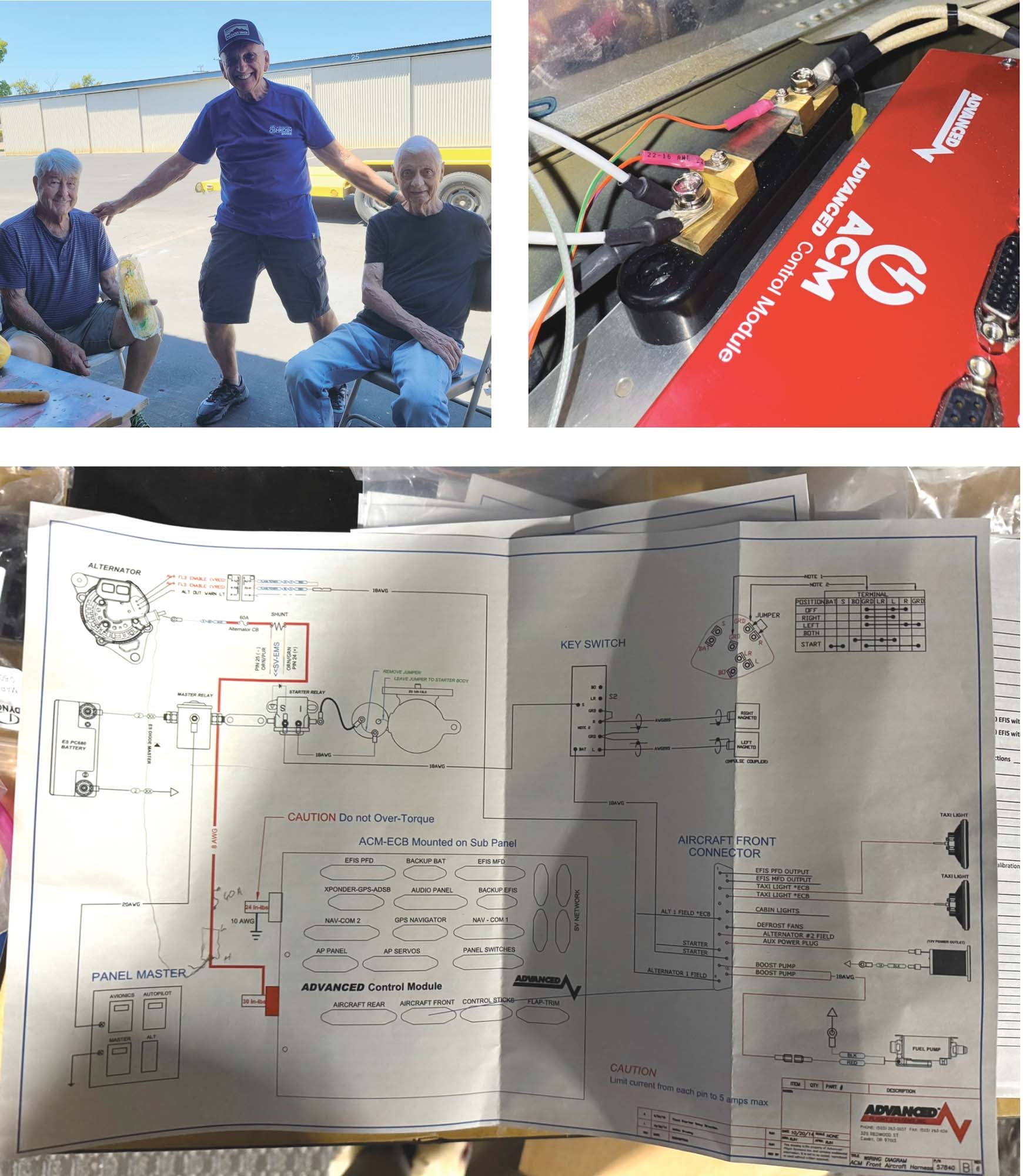
Fortunately, yet again I have the help of my friends. Hal Pattenaude, electrical engineer; Nick Leonard, telecommunications expert; Stan Lawrence, CFI and builder of five different Van’s RVs; Kerry Richburg, handyman and aircraft builder; and Bruce Walters, land planner and builder/restorer of an RV-3 and RV-7. With this crew, how could I lose?
Moving the Volts and Amps Around
In going with the Advanced Flight Systems panel, I also decided to go with the ACM—Advanced Control Module. This is an all-in-one electrical control system with internal circuit protection. I won’t need many regular fuses or circuit breakers because the ACM takes care of that. It also connects to the EFIS to show system functions and ties a bunch of other items together. It also makes connecting the rest of the avionics simple but there’s still some integration to the airframe.
The electrical system revolves around the battery and Stan is particularly happy with the basic setup in my RV-6. In truth, it’s a pretty common 12-volt, single-alternator arrangement. On the ground side, the battery wire goes up to the firewall and through a big pass-through terminal. The positive end goes to the master relay then to a copper strap connecting it to the starter relay. In between the master and starter, there’s a wire that connects to the output side of the master relay that is the connection to the shunt, which then takes and measures the power via a short piece of wire to the Advanced Control Module (ACM), which powers the rest of the airplane. In this way, the shunt is measuring the alternator’s output (the load) instead of measuring the charge rate of the battery. Some builders might put the shunt on the firewall or closer to the alternator itself but we reused some old wire and decided on a different path.
In part this is because the ACM is mounted forward of the subpanel—for those of you not RV-6 conversant, that’s an area formed by a bulkhead ahead of the main instrument panel but behind the cabin side of the firewall. Normally the alternator output comes to the same stud on the battery contactor as the main supply but we moved it to the stud on the ammeter shunt instead.
I mentioned something about little wires before. Everything on the battery and alternator side is big, but Stan showed me how to cut away the insulation and add a wire terminal to attach to the shunt. Once we crimped it onto the wire, we shrink-wrapped black heat shrink tubing (or as I like to call it, “black shrinky dink stuff”) over it using a heat gun. It pays to be neat.
New Fuel Selector: Very Important!
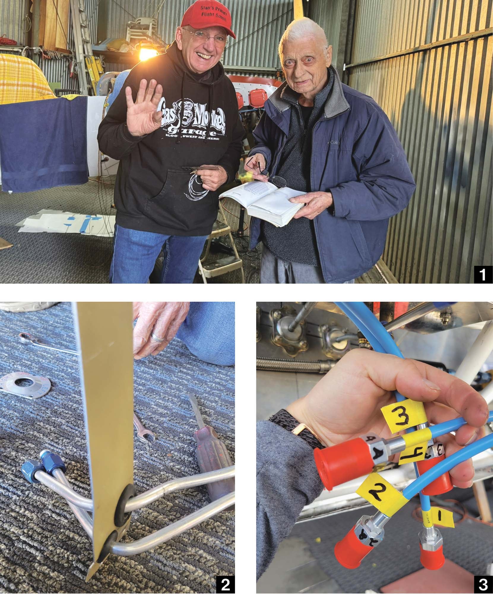
Upon first glance, the nice new Andair fuel selector that N2165U came with had no issues. It had left, right and off positions. Oh, wait. Take a closer look. The top of the fuel selector had been cut off and was no longer a perfect circle. For it to fit on the mount, the tops and bottoms had been lopped off and in the process a word had been, too: both. This airplane had been flown with a fuel selector intended for high-wing fuel systems and, worse, the wording indicating this to the pilot had been removed to make the whole thing fit.
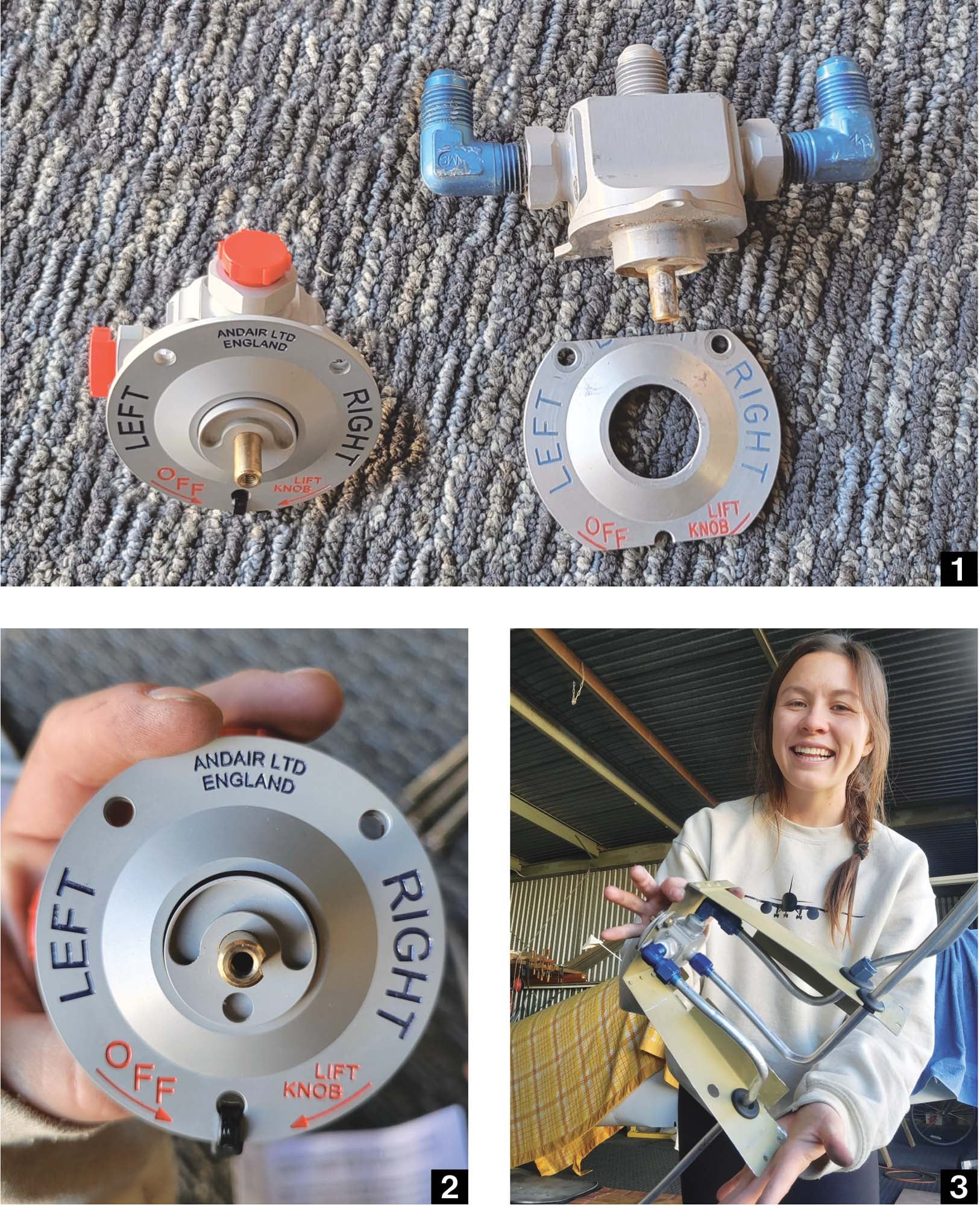
Obviously this had to change. Like most Van’s RVs (so far!), my RV-6 is a low-wing aircraft with the fuel tanks mounted in the wings. Because gravity alone isn’t enough to move fuel toward the carburetor, you need pumps; in my case it’s the engine-driven pump. Why is a both position bad for a low-wing airplane? Imagine flying on the both position and one tank runs dry. The fuel pump is likely to suck air and even though there’s fuel in the other tank it might not get to the carburetor. My dear friend and mentor Nick Leonard noticed this and generously bought me the proper Left-Right-Off Andair fuel selector.

Considering the old fuel lines were in poor condition and that Nick sponsored the new fuel selector, I decided to create new fuel lines, as discussed in previous articles. After bending those, my dear friend Hal Pattenaude helped me attach the new Andair fuel selector to the mount. The way it was mounted in the airplane required the top of the fuel selector to be cut off, which was unfavorable. Hal suggested adapting the new one, saying “you could use that on the new one that’s cut off.” To which I replied, “But I like the new one. It’s pretty! And it’s new!” Hal laughed. We decided to try to keep the new fuel selector as is.
Earlier in the week, Stan found some used fuel fittings at the local aircraft salvage yard, Kenny Faeth’s. Hal and I worked together to clean and attach some of those used fittings. After that, we fed the lines through the fuel selector mount and squeezed rubber bushings around them. Hal and I tightened the B-nuts around the fuel lines to ensure they would fit. Everything looked great—thank you, Hal!
New Ignition Harness
The ignition harness for the old magneto was worn out, so Stan and I went back to Kenny Faeth’s and searched for one in better condition. Unfortunately, the supply of Slick magneto harnesses was very limited so we took what we could get. After attempting to test fit the only two available, we discovered the springs inside the terminals were broken. They also did not appear to be the correct size for the spark plugs. In the end, I ordered a new one that came in a pretty blue color that matched my panel. I love saving money and salvaging perfectly good old parts, but sometimes new parts are necessary.
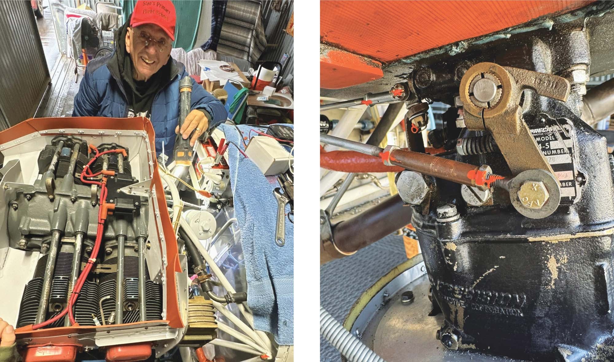
I labeled each wire on the ignition harness with yellow tape and a number so we would know which cylinders they went to. Stan instructed me to buy new Tempest spark plugs. I installed them with a droplet of VersaChem anti-seize on the threads and fresh copper gaskets. It’s great to have one part of the system complete, another item checked off the still very large list.
This completed the second half of the ignition system. All top plugs are fired by a Light Speed Engineering electronic ignition, with the coils mounted on top of the engine spine and firing automotive plugs. This setup gives me a simple mechanical backup (the magneto) along with the improved performance of electronic ignition.
Fixing the Mixture Cable
The next part of the engine we needed to work on was securing the new mixture cable. It was especially tricky because the 3-foot cable was too short and the 4-foot cable was too long. After some trial and error, Stan managed to figure out a way to run the 4-foot cable underneath the panel floorboard, through the firewall and an additional support, then to the attachment arm. He’s so good.
Since the cable comes in from a slightly different direction than it had before, we had to figure out a way to get the cable end to the mixture arm on the carburetor. This required a bit of trial and error that’s still ongoing. We did know that the cable needed to be offset from the firewall with a spacer. Our goal was to make sure the cable moved freely and that it had the right amount of throw to fully engage the limits at both full-rich and idle-cutoff positions. I’m told this is a critical issue and we want to be sure we get it right. Fortunately there are different mixture-control arms available for the Marvel carburetor, so I’m sure we’ll figure it out.
Wait, Still Painting?
So guys, I got a bit ahead of myself a few editions ago. It’s easy to lose track of when things happen during the rebuild process. Stan and I dropped off the fuselage and wings to our friend Justin Frei, who owns an auto body shop. Justin and his amazing team prepped and painted the fuselage with record speed. In only three weeks, they had the fuselage ready for pickup so that we could start mounting the engine and wiring the panel. Within a week and a half of the fuselage pickup, they also managed to completely paint the wings.
The fuselage and wings were the biggest pieces, but the control surfaces and miscellaneous parts still needed painting. During our trip to Justin’s to pick up the wings, Stan and I dropped off the control surfaces and would bring the miscellaneous parts later. The control surfaces included the rudder, horizontal stabilizer, elevator, ailerons, wingtips and flaps. The miscellaneous pieces included the canopy, upper and lower cowling, gear leg fairings, wheel fairings and spinner.
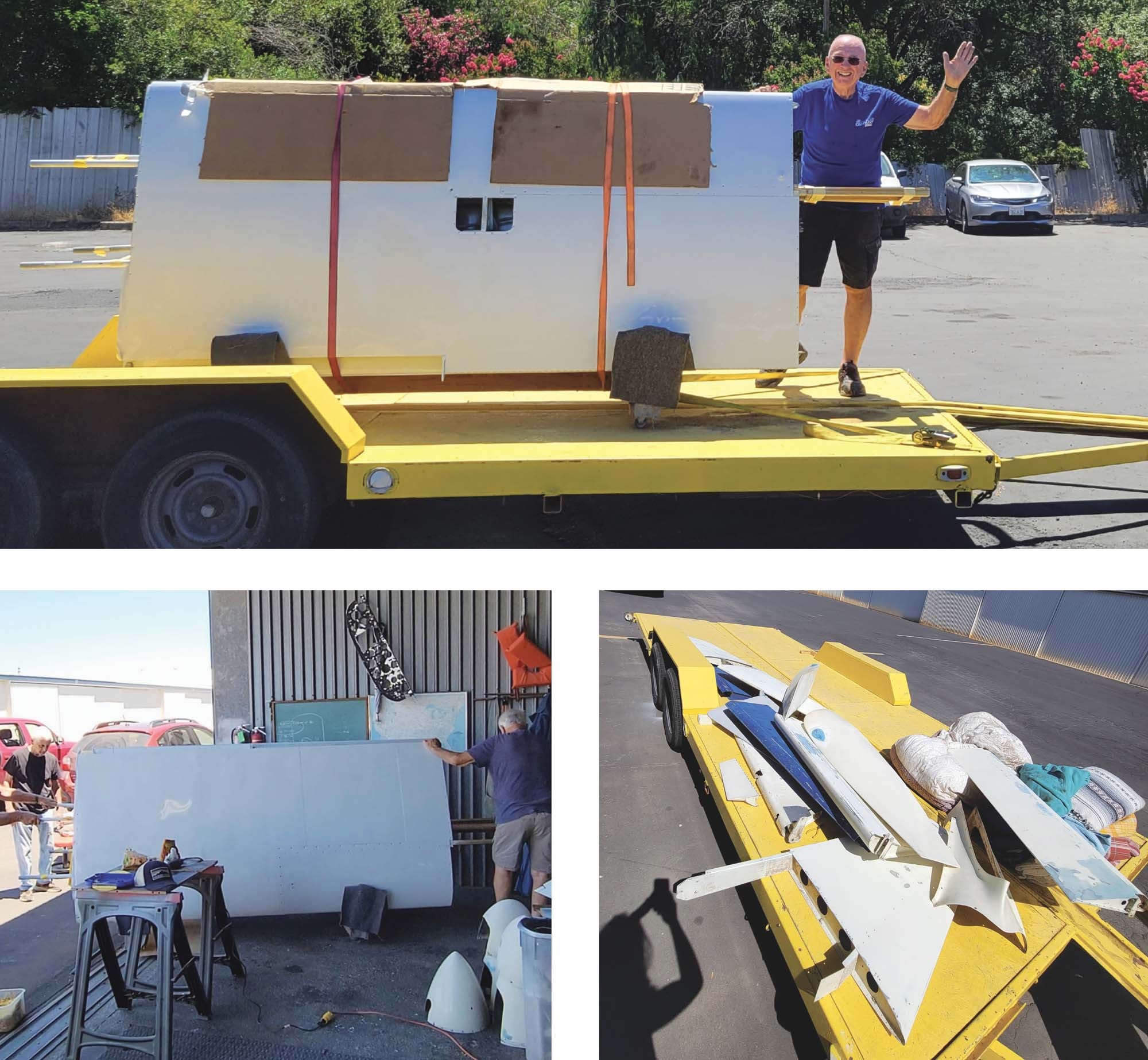
Stan, our dear friend and expert handyman, Kerry Richburg and I met early in the morning and carefully loaded all the large control surfaces into the back seat and truck bed of Stan’s Honda Ridgeline. Using old tires and many blankets, we wrapped them up like little baby burritos to ensure they would not get damaged in transit. Stan and I slowly drove to Justin’s shop, pulling the trailer behind us so we could pick up the wings. I was ecstatic when we pulled up to see them sitting on the wing rack in the parking lot, pearly white and shiny in the sun. We ratchet-strapped the wing rack to the trailer, then carefully ratchet-strapped the wings onto the wing rack using cardboard pieces so the skins on them would not get damaged. Upon arriving back at Hangar 32, Kerry and Hal were there waiting for us. The four of us delicately pulled the wing rack off of the trailer. We flipped the wings around in the rack so they would sit on the leading edge. Stan was impressed. “They look beautiful,” he said.
Miscellaneous Projects
We continued to work on firewall pass-through work for both wires and controls. Stan ordered many different wire protectors so that we could wrap the wires and send them through the firewall together. He also attached Adel clamps to the valve covers and cleaned up some of the messy wiring with zip ties.
While this is not a miscellaneous project, sometime in here someone (I’m actually not sure who) came by and installed the propeller. I am so excited it is starting to look like an airplane.
The hangar is so messy that oftentimes, we forget where we put things. Stan finally found the baffle screws after searching for a whole 20 minutes! We screwed the final parts of the baffling on, but we still needed to secure the curved cylinder baffles to make them fit closer to the cylinders. Somehow the wires that connect the baffles beneath the cylinders went missing, so Stan showed me how to make new ones starting with stainless wire and using a die to make the threads. Once the wire threads were completed, we put plastic tubing over them so they wouldn’t rub on the cylinders. After that, we simply ran the wires underneath each cylinder, put a nut and washer on each and tightened them down to create tension. We could have purchased prefabricated versions but it’s so much more interesting to make your own.
Lastly, we added a flexible seal to the fixed baffling. After marking where we needed to put holes in the silicone strip, my younger sister, Arianna, stopped by and I showed her how to punch holes in it. Then, we worked together with Stan to screw the rubber onto the baffling. He clamped the baffling down so that the rubber would start to “get trained” into a curved shape. Officially done with the baffling. Finally!


