 I find it unsettling to cut a hole in a perfectly good fuselage, but there are times when it needs to be done. In this case I needed to provide access to bolts associated with the horizontal tail of my T-18 project. Browsing the Thorp forum and examining T-18s at Sun ’n Fun convinced me that I would later regret the lack of access panels if I did not incorporate them during the build phase.
To get dimensions, I measured the area for the openings on completed aircraft, plus I cut some openings in cardboard to see how comfortably my hands would fit. I settled on 3.5×3.5 inches as a good size for the opening. Don’t forget that the access cover will be that size plus enough on each side for edge distance from the screw holes, about 0.30 inch to either side of the holes.
To be honest, the edge distance for the screw holes is not critical since it is a loose-fit hole that should not have sideways forces creating a tear-out situation. In my case, that meant 4.7×4.7 inches for the cover itself. To provide edge distance for the attach rivets, I added yet another 0.25 inch on either side of the fastener row, so the doubler itself winds up with overall dimensions of 5.7×5.7 inches. Size yours accordingly depending on the size of your hands and what needs to be accessed, especially if you need to get a tool through the opening.
One problem was how to smoothly create a rectangular opening and minimize sanding and filing afterward. Using hand shears will distort the cut edges, plus they are unwieldy for smaller, internal cuts. To get a better result, I turned to a technique I read about some years ago: using a knife instead of shears to cut the metal.
Making Holes
The trick is to score the metal to create a bend line with a V-shaped groove in it, i.e., a stress riser. On thinner metal, 0.020 to 0.025 inch thick, I have cut all the way through in about 20 or so passes in a situation where there weren’t any free edges. If there are free edges and you are able to bend the metal, five or six passes will be enough.
A good rule of thumb for skin doublers around openings is to go a gauge thicker than the parent metal. With 0.025-inch fuselage skin, that meant I needed 0.032-inch-thick doublers. But in a senior moment, I forgot that I had re-skinned my outer wings a gauge thicker. This meant that the old skins I was using as raw material were only 0.025-inch 2024-T3, not 0.032. Oops! And when I did make the second set, I observed that 0.007 inches of thickness does make a noticeable difference in being able to bend the metal. (No, I couldn’t think of a good 007 reference there.)
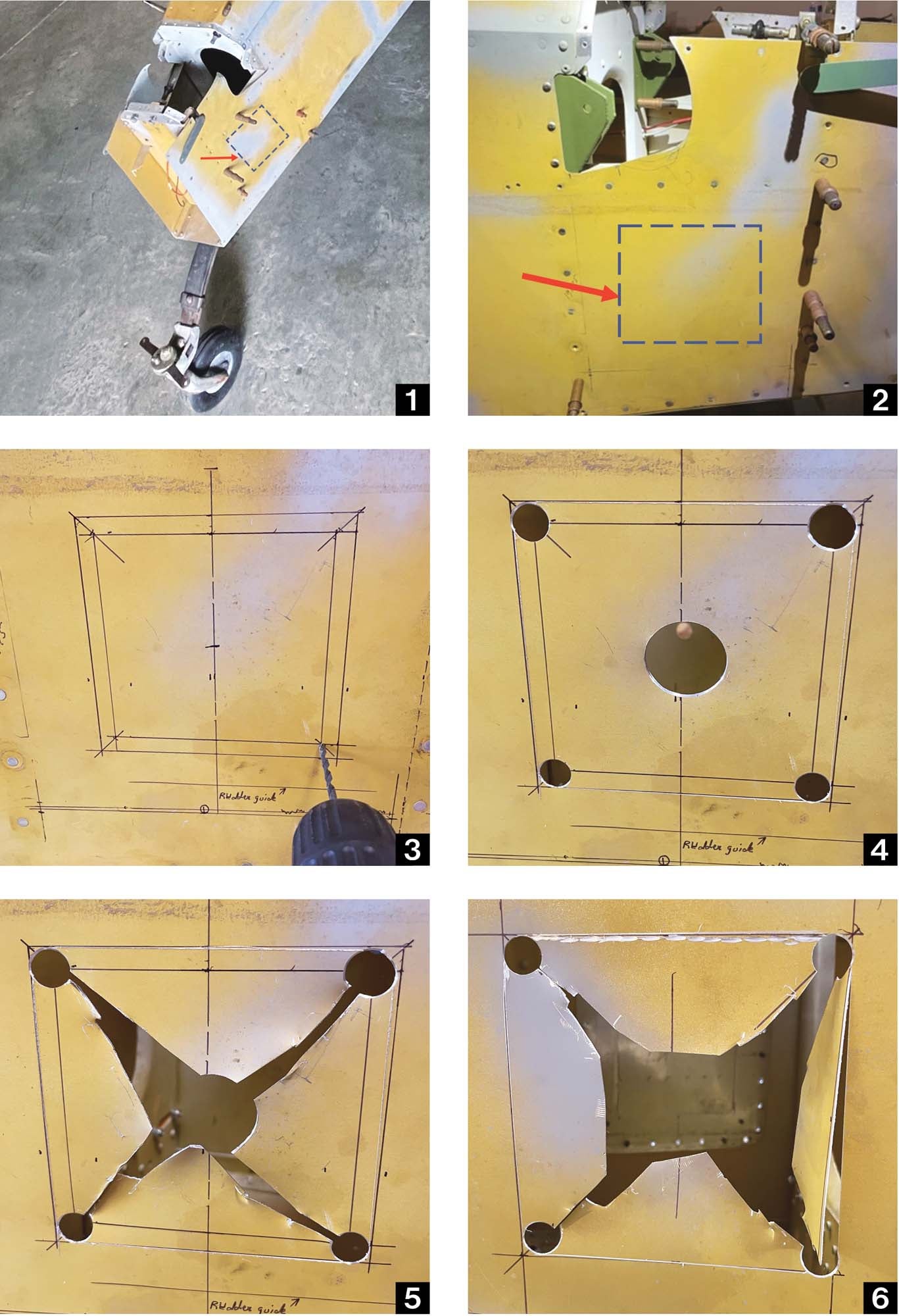
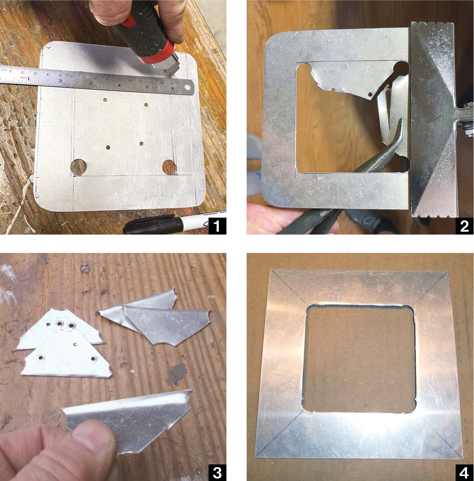
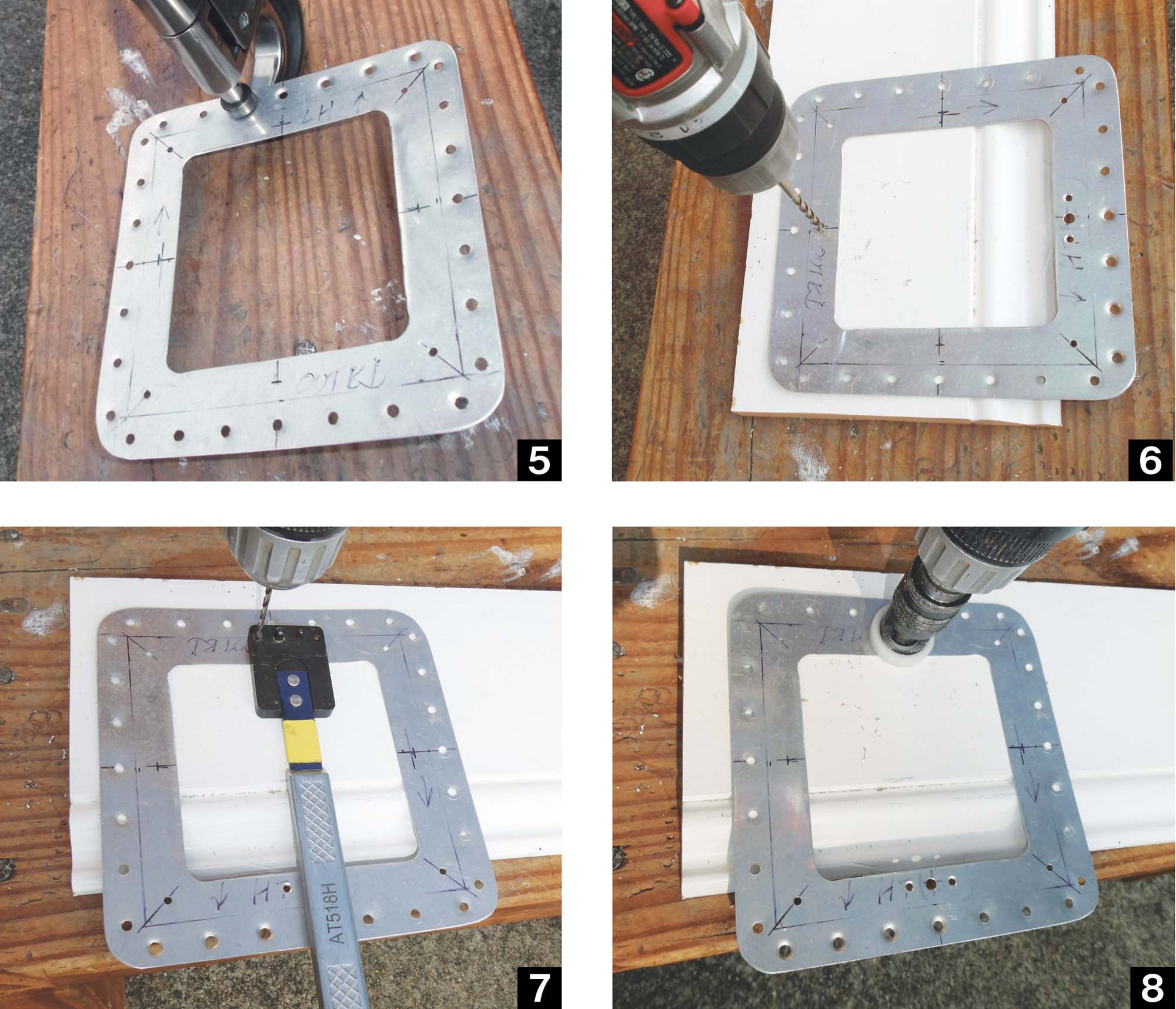
For thinner gauges, you can use a disposable craft knife, but my preference is a hook-shaped knife for cutting vinyl flooring. I found mine in one of the aviation aisles at a big-box hardware store. After determining dimensions, I laid out where to have corners with a 0.25-inch radius and drilled them out. For thin sheet metal, the best results come from drilling a pilot hole with a 1/8- or 3/16-inch bit and then using a Unibit step drill to take the hole up to a 0.50-inch diameter. For this I used a cordless drill and slow rpm to minimize the bit wanting to “walk.” Even so, it will try to walk (don’t ask me how I know this), so take your time.
With the corner holes drilled, drill a large hole in the center of the metal to be cut out. Drill it as large as possible, as you will use snips to cut from this hole to the corner holes. Be sure to clamp the work, as the bigger the hole, the more the bit wants to grab the work and turn it, possibly leading to you needing bandages.
After getting the holes drilled, use a fine Sharpie to lay out a cut line tangent to the holes. Use a metal straightedge to guide the knife, taking care not to score the metal past the tangents of the holes; I used the steel ruler component of a vintage square. If possible, clamp the straightedge into place.
Draw the knife down the line at least five times for 0.025 inch or thinner and up to 10 times for 0.032 inch. The goal is to make all subsequent passes in the same groove as the first pass. If you look closely, you should see a tiny ribbon of metal shaving being removed with each pass.
After all four lines have been scribed, use your snips to cut from the center hole to the corners. You may have to cut out wedges of metal to get all the way to the corner without distorting the surrounding metal.
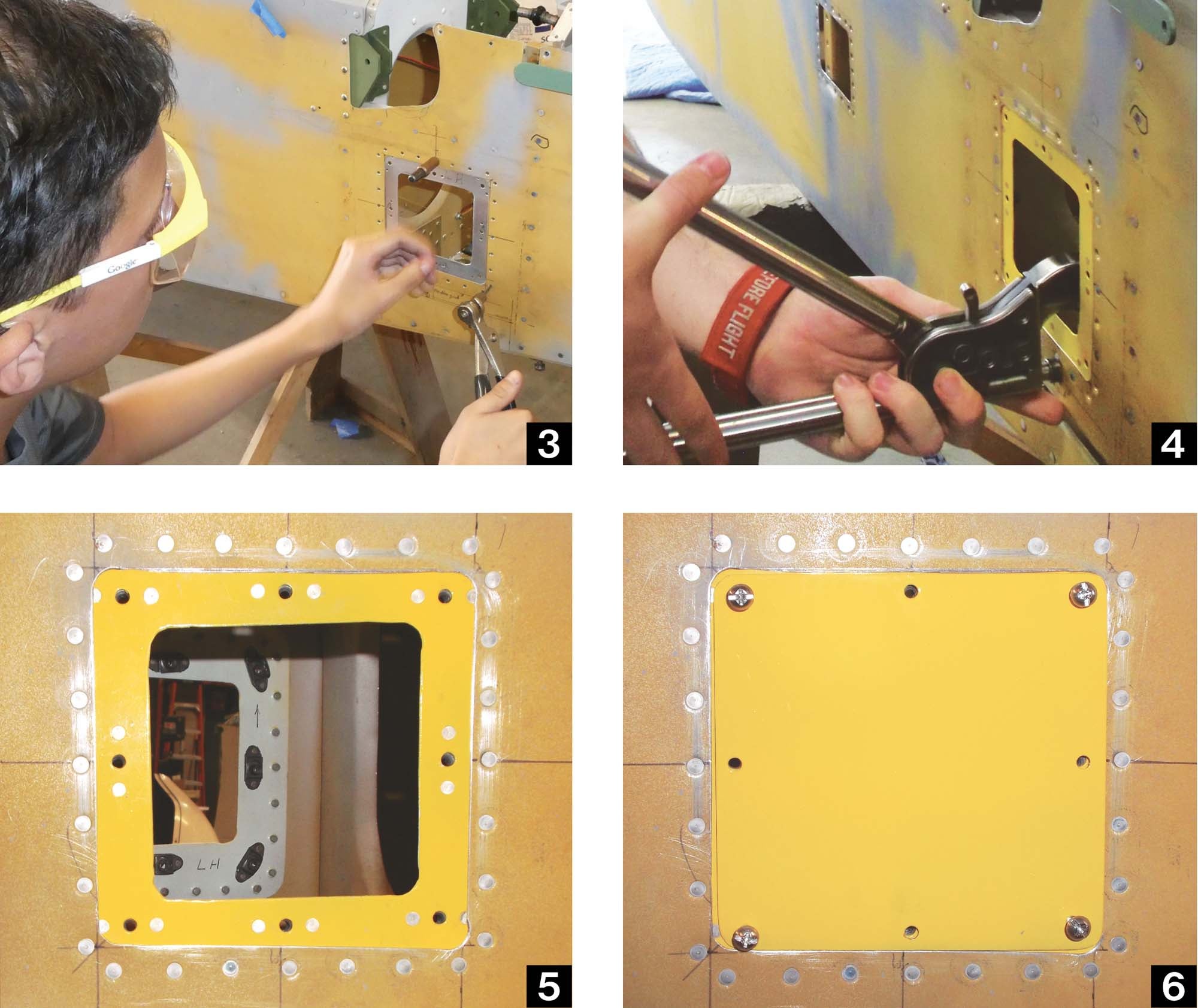
You will now have four triangular pieces of metal still attached at the scribe lines. Clamp the doubler along the line so that when you bend the triangular piece over, it does so at the scribe line. With the 0.025-inch versions, I was able to hold them in a crimping tool and easily bend the to-be-removed pieces with pliers or a gloved hand. With 0.032-inch metal, it was much more difficult and would have been easier (if I were patient enough to wait until I was at the shop) to clamp it in a vise. In either case, the pieces usually snapped right off on the return motion after being bent 90°, a good reminder as to why we smooth and blend scratches in the skin and work so hard to prevent stress risers.
After removing all four sections, a few passes with a file were needed to clean up any places where the edge didn’t have a clean break or the cut line wasn’t exactly tangent to the corner. I then dressed the edges with some emery cloth. Remember that you’ll be reaching through this opening, so smooth edges are very important.
The openings in the fuselage were cut the same way as the doublers except that it wasn’t feasible to clamp the edge of the scribe line. Fortunately, with the side skins being 0.025-inch thick, it was easy to bend the pieces by hand (wearing work gloves) and they popped right out.
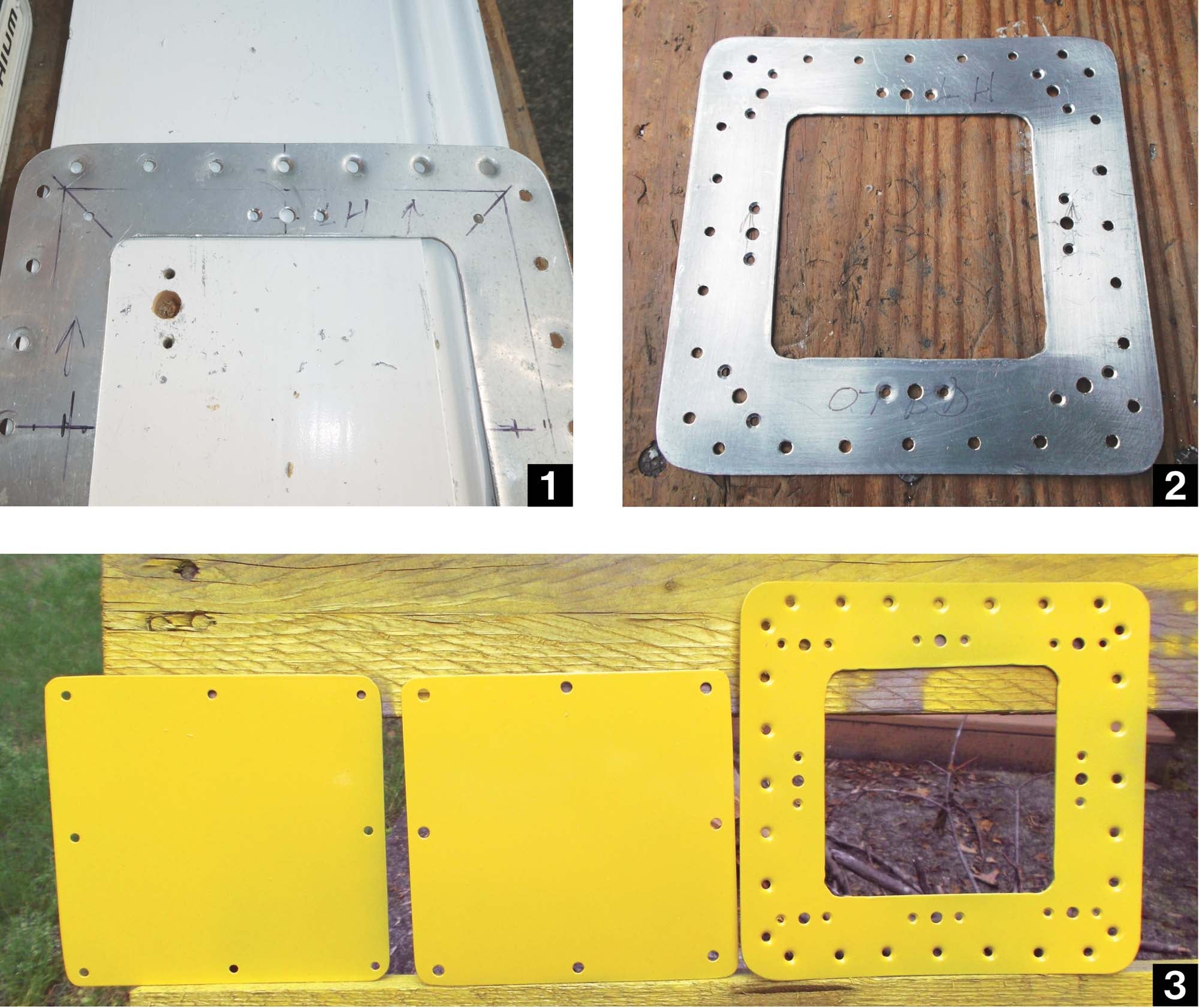
In both cases, there is no distortion of the parent metal from the shears, nor is there a ragged line from trying to get snips parallel to the cut line. Notice how much the metal is distorted in the cuts to the corners versus along the scored lines. Yes, you can also cut out an opening with a cutoff wheel, but for thin metal this is just as quick and easy, and there’s less risk of an uneven cut due to a miscue or slip of the hand. One of the photos shows where I initially was going to use a cutoff wheel before switching to a knife.
Rivet Locations
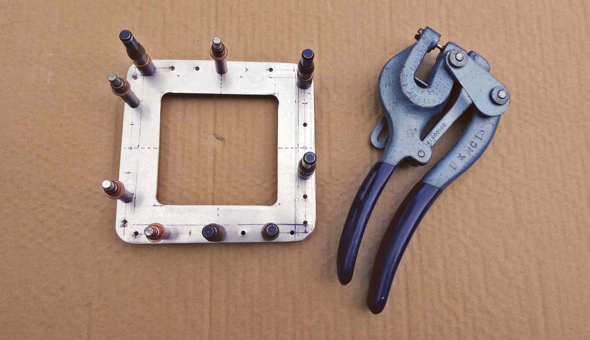
After fabricating the doublers, I laid out the rivet locations and marked them with a spring-loaded center punch (again located in an aviation aisle at the hardware store) to be followed by punching them out with a Whitney punch. If you don’t have one, a Whitney punch is invaluable for making clean holes without a drill bit possibly “walking.” Drop the nib of the Whitney punch into the punch mark and squeeze. The holes will be ⅛ inch, but easily drilled out to #30 in the next step. The Whitney punch is also very quiet when you are working in the garage and someone is trying to nap in the adjacent room.
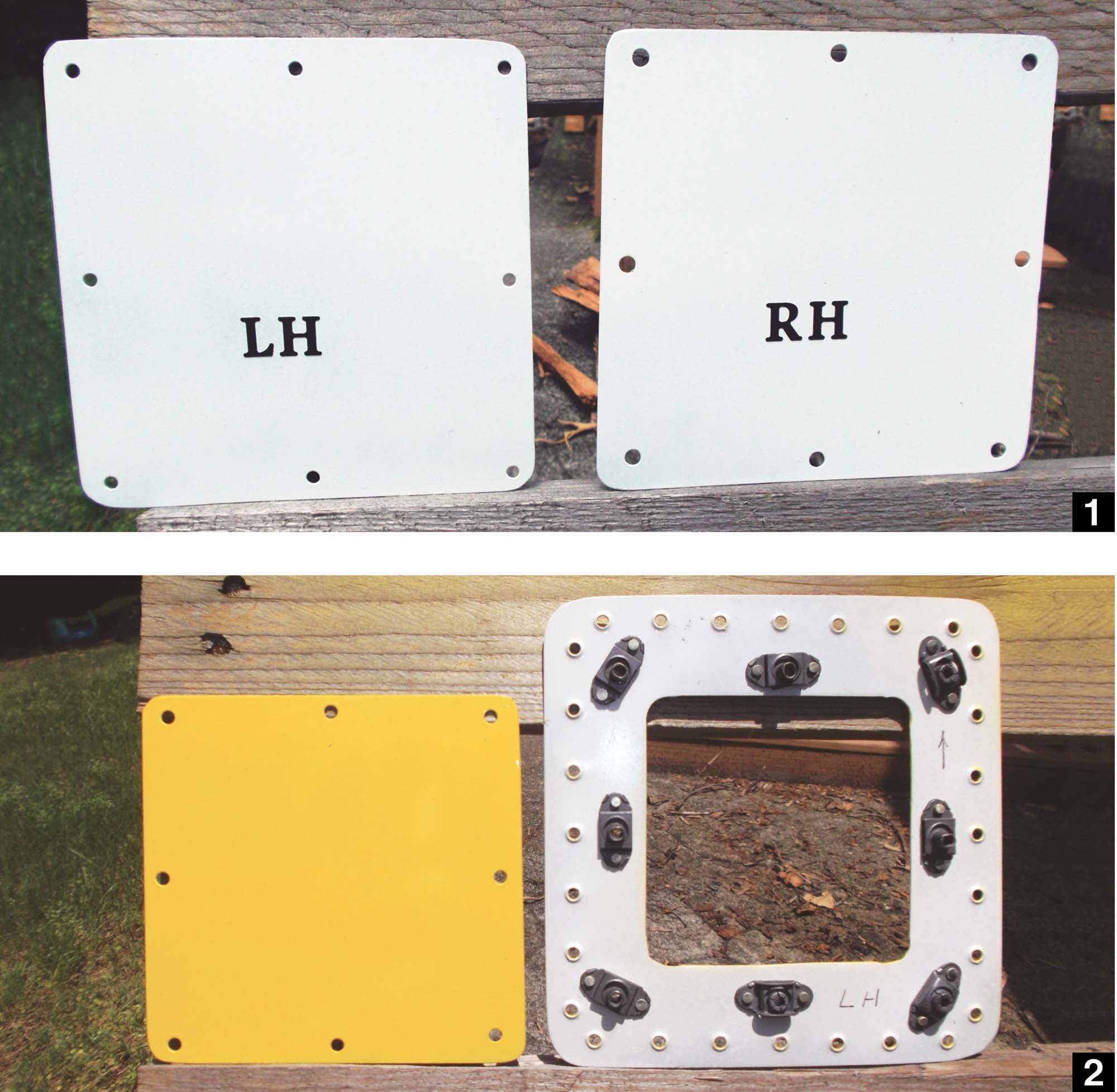
The cover plate material is cut slightly oversized and then held up to the fuselage openings to trace the exact shape. After the plates are trimmed for a close fit to the fuselage, they are Clecoed to the back side of the doublers and used to center the doublers over the fuselage opening. The doublers are then match drilled to the fuselage openings; be sure to mark them afterward since they are now “handed” and directional. Yes, in theory they are identical, but minor deviations during backdrilling mean they now fit one side better than the other, plus the fuselage openings may not be perfectly square/rectangular.
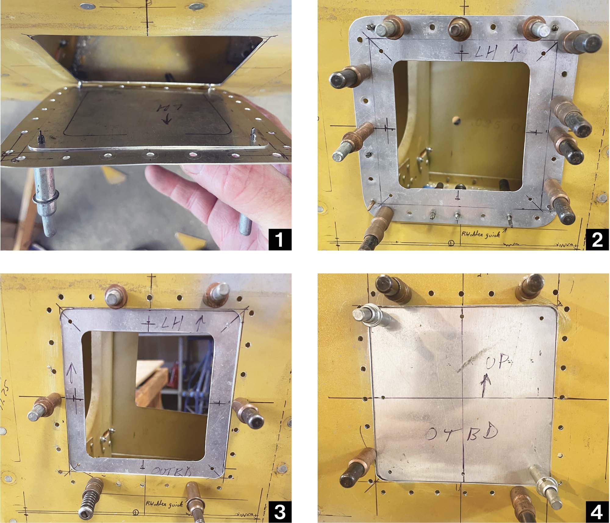
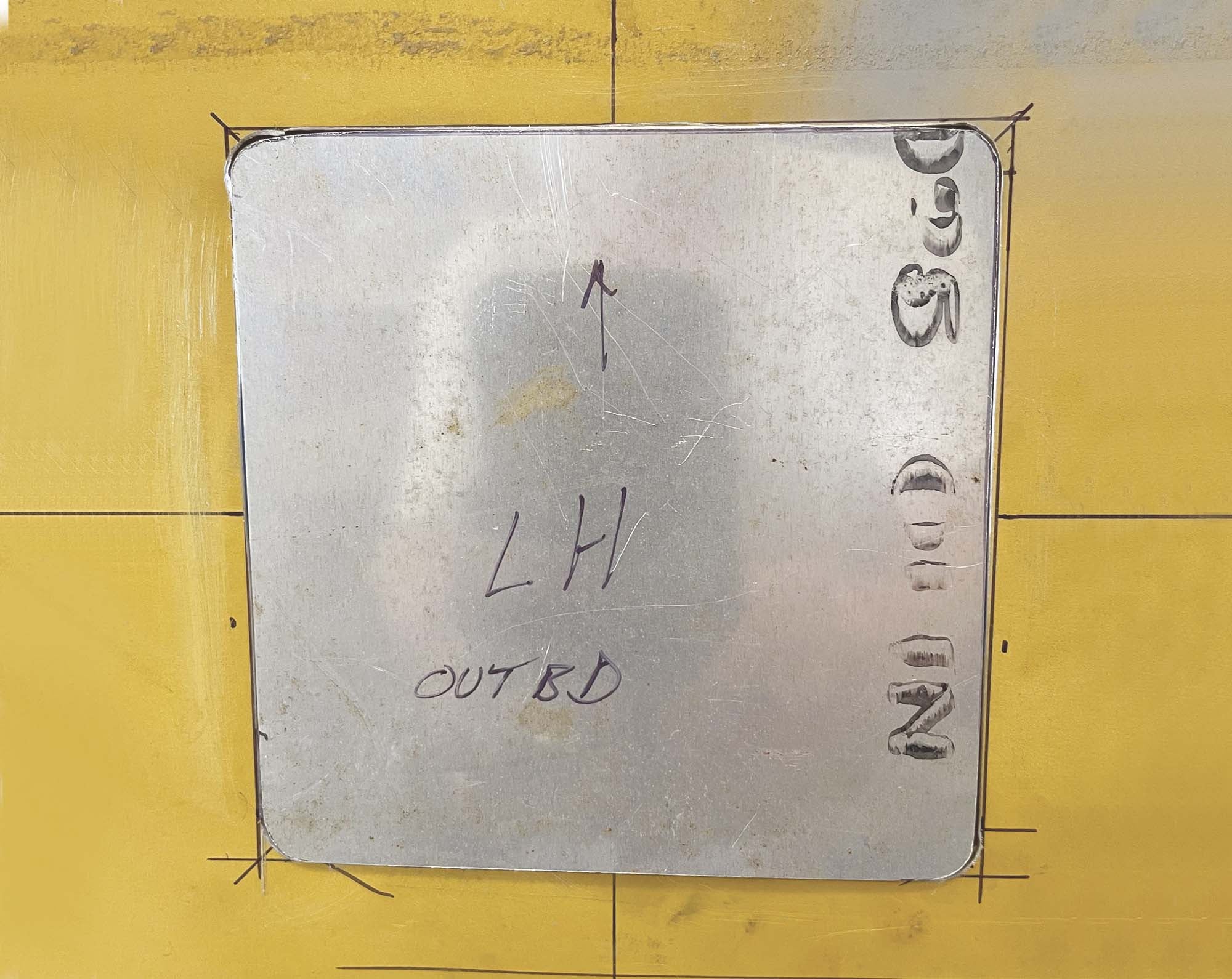
Use a Sharpie liberally to know which side faces out and which way is up. Since the fuselage itself is used to trace each access panel for its final shape, even if the fuselage cutouts are not perfectly square, they will have a very close-fitting cover tailored to that opening. Due to the Unibit drifting once or twice (no comment), my openings are not quite the precision geometric shapes that I wanted, but they are close and it will be difficult to discern that because they are located under the horizontal tail.
The cover plates will be held in place with #8 screws going into floating nut plates. Drill the screw holes using a #19 drill bit. This hole will be used to center your nut plate drill jig. Don’t have a nut plate tool? Then get one. I tried do it once without the jig by putting a screw in the nut plate and backdrilling the attach holes, but the results are far less than optimal. Spend the money for a nut plate tool; you will thank yourself later. The nut plate tool is placed in the screw hole to drill one attach hole, then flipped over for the second hole. The attach rivets are 3/32 inch, so a #40 bit is used.
For the cover plate to fit flush, countersunk rivets are needed to attach the nut plates. The head height on a 3/32-inch solid rivet is about 0.036 inch, making it difficult to countersink holes for them in 0.032-inch metal without knife-edging the holes. Because of this, I set the countersink tool to leave the heads protruding by about 0.005 inch, which won’t be a factor in this application. Why? Because installing the rivets will squeeze the heads down nearly flush, and the inside of the cover plate won’t care if the rivets stand proud by a few thousandths of an inch afterward.
The dropout pieces removed earlier served as scrap metal to get the countersink tool set. A scrap piece of molding makes for a flat surface for drilling and using the countersink tool. A ¼-inch hole in the wood allows the tip of the countersink bit to drop below the plane of the metal. Take your time and check the fit of the holes after countersinking.
The rivet squeezer is again employed, this time to set the nut plate rivets. The nut plate itself will prevent getting the squeezer anvils centered on the rivet, but get it as far onto the rivet as possible. If it does slip, you will likely put a crease in the rivet head. Carefully resetting the tool on the rivet and giving another squeeze is usually enough to flatten out the rivet head instead of having to drill it out.
Sharpie Advice
Regarding the Sharpies and markings, here are some lessons learned over the years.
1. With bare sheet metal, it is very easy to confuse which side faces out or up, and sometimes which pieces to keep or discard when cutting. This is especially true when a work session is interrupted and time passes. Conversely, there’s nothing like finishing a part and realizing you have all the dimples or countersinks going the wrong way. (No, I didn’t do that this time, but I may or may not have done so in the past). Get used to using a Sharpie (never a pencil!) to make copious notes on the metal. It will later wipe away with acetone when you are ready to paint and save potential errors and rework until then.
2. Since the Sharpie will wipe off during cleaning, make sure to keep the part(s) oriented when cleaning them so that you still have that knowledge after painting. The best thing to do is to immediately re-mark with a Sharpie on the back side of the part after cleaning and paint right over it; you can typically read the Sharpie through the primer. If need be, paint one side, then use some blue painter’s tape to mark on and keep things straight while painting the other side.
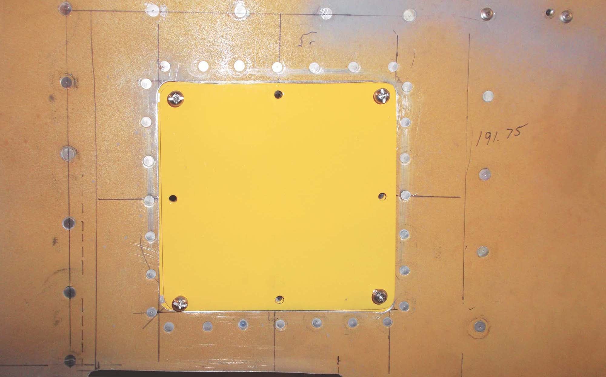
In the case of the access covers, I painted them white on the inside and then applied the LH/RH labels before applying a coat of yellow on the outside. For the doublers, I was able to see the Sharpie markings through the thin coat of white. Even so, after painting was done I made additional marks to make sure the kids and I install them correctly during the next youth-build session.
Was the white necessary on the inside faces? No. I could have left them bare metal or in primer, but to me it looks sharp, especially with the nut plates installed. The outside faces of the doublers were painted yellow with a rattle can so that any overspray when painting the airplane will blend in with the existing color instead of looking like, well, overspray. Why paint the outside of the cover plates? Just to have them look nice for y’all.
That about, er, covers it. Next is an inexpensive taillight with a housing that’s easy to fabricate.


