Stay with me here. This is going to be a very interesting and somewhat difficult project. But worth the read, I guarantee.
No matter how many strobes you have on your wings and lights all over your airplane, the regs require you to have an “anticollision light” on board your airplane to fly at night. The light must meet the requirements of Regulation 14 CFR 25.1401, which is one of the more difficult technical FARs to interpret that I’ve come across in my career.
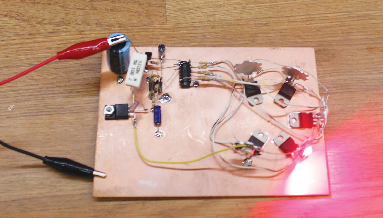
If you fly a classic (1950s era) aircraft, you probably have an incandescent reflective bulb mounted on a motorized rotating plate on the top of your vertical stabilizer. Today you can somewhat meet the requirements with a flashing strobe mounted on the same location. I’m going to take you back to the 1950s era with an LED unit designed to mimic those classic softly rotating lights with a modern twist.
You can still buy the rotating beacon design, hard to find in the 14-volt version, and it starts at $300 or so from several parts sources. Parts for the one in this article are about $25–$30 if you want to design a PC board for it.

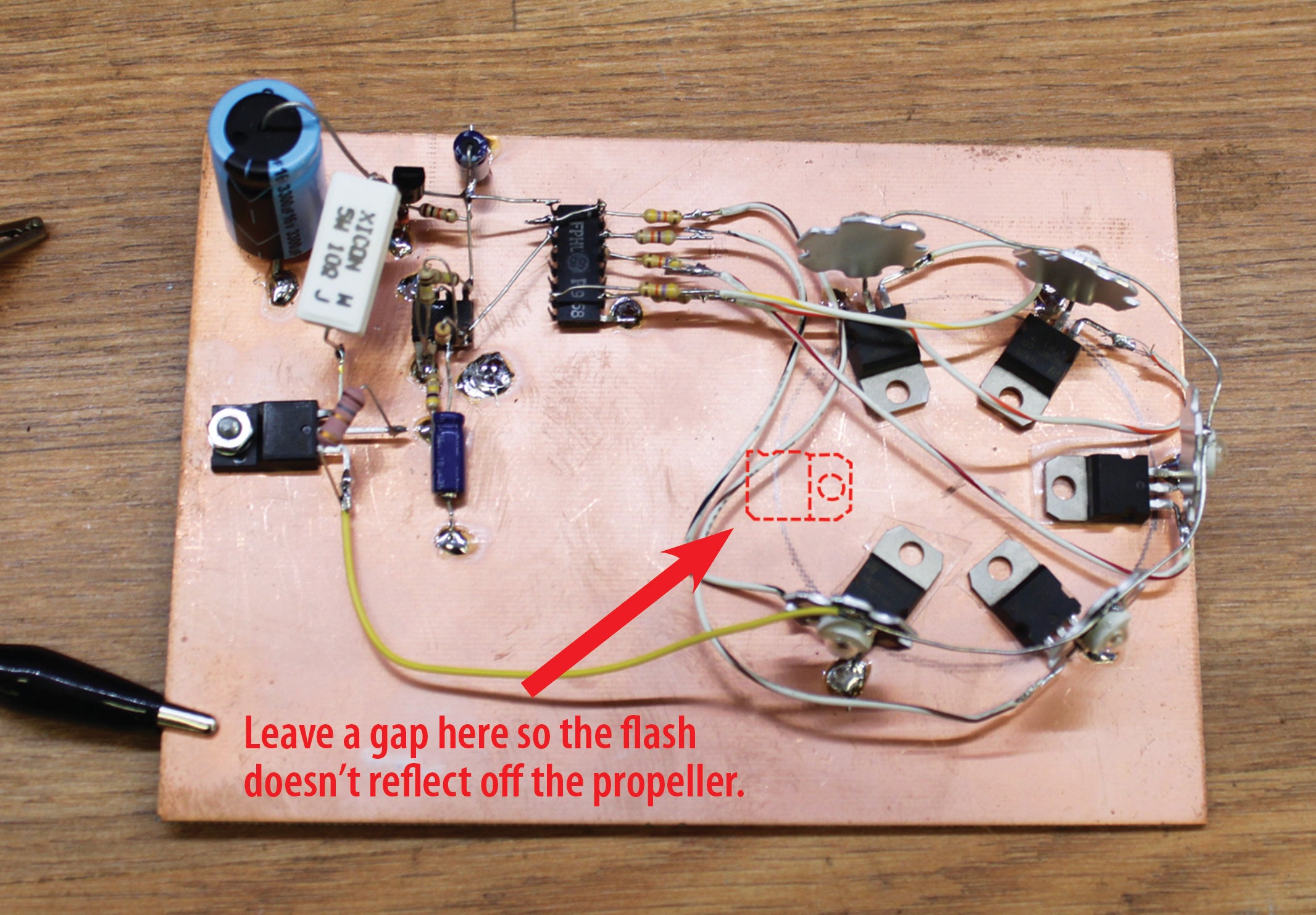
I’m going to start with the lights themselves and then work my way back through the drivers, the counter and the clock that sets the pace for the whole array.
The LED lights that I used are probably not what I would use if I were going into production on this design. However, they meet the regulation design goals for brightness and are relatively inexpensive ($3 each). They far exceed the brightness of the incandescent design of the 1950s, in that the incandescent bulb had to shine through a red lens that brought the efficiency of the generated light down to roughly 15% of the bulb’s white light—and that is on top of the very poor efficiency of the bulb’s conversion of electrical energy to white light. The LEDs convert electrical energy into pure red light directly. They run remarkably cool even though they are rated at 3 watts. (Sidenote: They are 2-volt devices that have a maximum of 700 mA, which is 1.4 watts. How they can be rated at 3 watts is a mystery to me.)
How bright are they? I can only use the MK-1 Mod—a light meter called my eyeball. I know what my airplane incandescent beacon looks like at half a mile up the taxiway. These little lights are subjectively much brighter at a mile than the airplane beacon at half a mile. If I were going into production on this design, I’d probably look around for a supplier that would put three LED chips in series into a single lamp. It would have made the power supply a lot easier to design and been three times as bright.
The prototype that I used for this article used all red LEDs. You can use all red, half red, half white or all white—your choice. They are all 700 mA devices and the power supply is capable of driving either color.

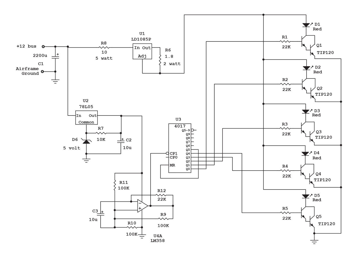
The drivers were an interesting design task. Somehow I had to turn each LED on at the right time and then off for the remaining sequence. Somehow I had to keep the drivers from overheating by asking them to dissipate large amounts of voltage at nearly an ampere of current. The easy way to do that is to put the driver transistors between the LEDs and ground and run them in saturation—full on or full off. That is, in the “off” mode for a particular LED, you would have full power supply voltage at zero current, which is zero watts. (Watts = voltage times current. Any voltage times zero current is still zero.) In the “on” mode you would have zero voltage across the driver at the full 700 mA, which is also zero watts.
Not only that, but the timer circuit can only produce a couple of milliamperes of driver current. How to control 700 mA with only a couple of mils of drive current? Remember last month we discovered that the Darlington transistor had a huge current gain for a miniscule driver current? The same is true here. Darlington power transistors aren’t all that expensive (75 cents each when you buy 10) and they have a current gain of 2500 or so. That means for a driver that can only put out 1 milliamp of current, the Darlington can switch 2.5 amps. We only need it to switch 0.7 amps (700 mA). Piece of cake.
The timer circuit is somewhat interesting. This is the first time I’ve introduced you to a whole new family of semiconductor devices called “CMOS” (complementary metal oxide semiconductor), pronounced “see-moss.” CMOS is an inexpensive “logic” family of about 200 devices. Logic says there are two states—high and low. Power supply voltage is high, zero volts or ground is low. (Or black and white, or up and down, or it am or it ain’t.) In this particular case of the 4017 device, you have a clock input, a clock reset and outputs that go from 1 to 10—the so-called “decade divider.” That is, all outputs start at low (zero volts). On the first high input to the clock, the Number 1 output goes high. On the second high input to the clock input, the Number 1 output goes back to low and the Number 2 output goes high. This repeats itself until the Number 10 output goes high and then all the outputs go low and the whole thing repeats itself every ten input pulses.

Now the trickery. We want our clock pulses to turn on outputs 1 through 5 sequentially to light LEDs 1 through 5. But then we want to reset everything after the fifth light. Simple: Take the Number 6 output, run it to the clock reset, all the outputs go back to zero and we start the whole sequence over.
The clock is a simple op-amp square-wave oscillator putting out a clock pulse about once a second. With five lights, this means that you are getting roughly 10 “revolutions” per minute.
Finally, the power supply. The lights need 700 mA at a constant current source to light properly. The LD1085 was turned into a current source with the addition of one 1.8-ohm resistor to make that happen. The problem was that turning 13.5 volts or so from a battery supply into a couple of volts for the diodes put a heat stress onto the regulator that I had to alleviate with a fixed-value, high-wattage resistor. In production, I’d put three or four LEDs into series to do a few things: make the lights much brighter and eliminate the regulator stress, and reduce the stress on our power supply.
The LEDs, TIP120 transistor and CMOS 4017 are available at All Electronics. The LD1085P, CMOS 4017, TIP120 and all resistors and capacitors are available at Mouser Electronics (www.mouser.com). The TIP120, CMOS 4017 and all resistors and capacitors are available at Jameco Electronics (www.jameco.com).
I hope you liked my step-by-step procedures in this article, and as always for next month…stay tuned…


The reg’s say anticollision lights can either be red or white. If I have enough strobes “all over my plane” that produce the amount of light to meet the regs , why do they need to be green or to be a “separate” anticollision light?
That should have been ‘red” , not green. Don’t know where that came from.
Strobes alone should meet the anticollision requirement if they have the required horizontal (360°) and vertical (generally 70° up and down) coverage. Whelen has a summary and diagrams on page 3 of their STC installation manual: https://flywat.com/pages/installation-guides
Wow, this article takes me back to my early electronics engineering days, circa 1975, when I started using the 4000-series CMOS chips. And these days I use MOSFETs if I need to switch large currents using logic circuits.