 When pushing my Hatz biplane back into the hangar after a flight one day, I noticed some oil on the stabilizer and also on the wing. A small amount of oil on the bottom of the fuselage was normal, if annoying, but this much was alarming, as oil leaking from a loose line onto the exhaust of my SA-100 Starduster a few years earlier had led to lots of smoke and a forced landing in a swampy field that didn’t end well (for the plane). I felt better when I remembered that I had gotten a little too slow over the top of a loop during that flight, and the brief zero-G probably let the oil spill out of the vent holes on the top of the breather catch can. It was time for a better solution.
The Starduster had an oil separator of unknown origin and design that presumably worked when oil wasn’t leaking from somewhere else, but the Hatz had nothing but a catch can or “slobber pot” installed by the previous owner, which was nothing but a metal can with some vent holes cut in the top attached to the end of the breather hose. Periodically, I would need to unscrew the can and dump it and more frequently wipe the oil that got through it off the bottom of the fuselage.
I had installed a homemade oil separator on the Mosler (half VW) engine powering the Fisher FP-404 I owned a few years back. That design was inspired by an older Tony Bingelis design but constructed differently. It worked quite well, so I took the same approach again for the Hatz, with some changes.
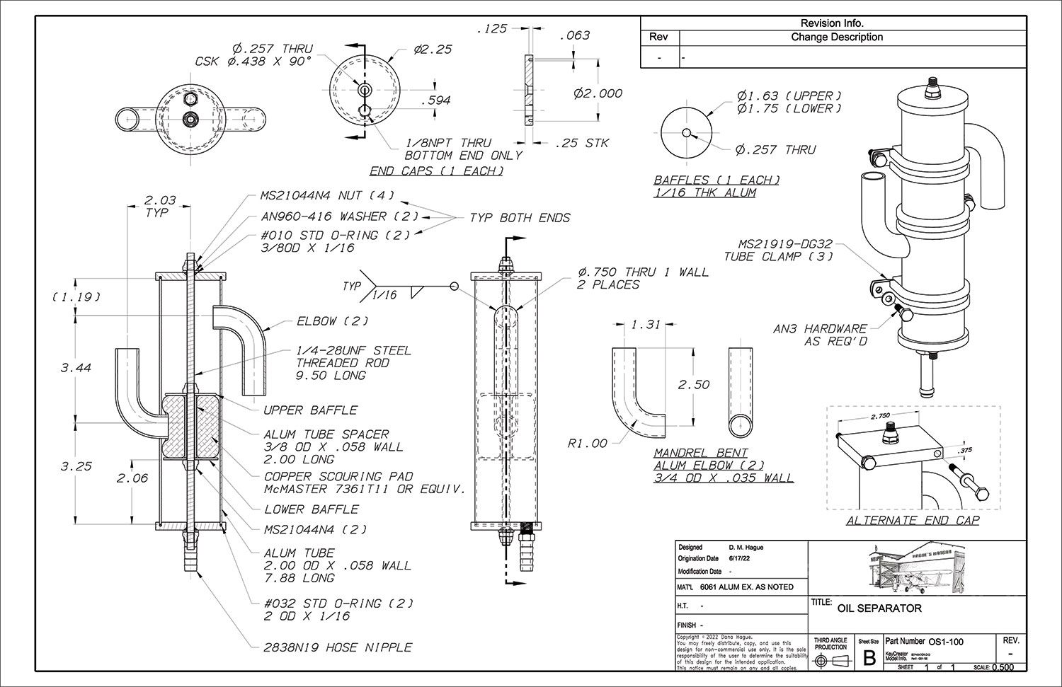
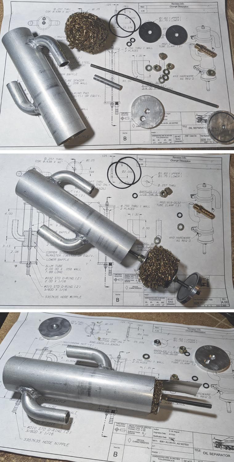
Tony’s design was a welded steel assembly, with several layers of wire screen to coalesce the oil from the breather vapors and let it drain down, with a concentric tube to vent the (hopefully) oil-free vapor overboard. My design was similar in concept but instead of welded steel, I used aluminum tubing with O-ring seals in the end caps, a threaded tie rod holding it together and supporting internal baffles, and a brass scouring pad instead of steel screen as the coalescing media. This construction allows the separator to be disassembled for inspection or cleaning, and the relatively soft brass pad would seem to pose less of a risk to the engine than a steel screen in the unlikely event a fragment got ingested.
Where Does the Oil Go?
There is some debate about what to do with the collected oil. Some prefer to hold it and periodically dump it as with the catch can, while others advocate returning it to the crankcase. The issue is that the breather passes not just oil mist but an acidic mixture of oil with water vapor and other blowby gases. As Dan Horton explained in “Separator or Condenser?” if the temperature of the entire breather system is maintained above the dewpoint of the breather gases, the corrosive moisture will not condense but will instead pass overboard through the vent, and the coalesced liquid will be only oil, which is safe to return to the engine. To do this, the separator must be mounted high enough so the oil can drain back to wherever the return line connects to the engine and in a location that keeps it warm enough that the water vapor doesn’t condense. On my Hatz, however, the can usually held a milky slime that appeared to be more water than oil—not surprising as the can was mounted in the cooling airflow on the bottom of the firewall.
On the Fisher, returning the oil to the crankcase was worth any potential downsides as the sump only held 2½ quarts, and there was a narrow acceptable range of oil…too much and the oil would foam from the crankshaft splashing the oil in the sump and causing a loss of oil pressure, and at only a half quart down it would starve the pickup in some flight attitudes. On that engine, it was a simple matter to return the collected oil because an existing check valve in the Mosler breather meant there was a partial vacuum in the crankcase for most of the cycle, which made it easy to continuously draw the oil back in through another check valve in the return line without relying on gravity.
The Lycoming on the Hatz is far more tolerant of oil level, however, so based on what I was seeing in the existing can I decided to forgo the return line, at least until I could see what, and how much, the new setup was collecting. The main goal now was to keep the oil off the bottom of the plane. Still, I would mount it high enough that I had the option of adding a return line later.
Pre-Build Considerations
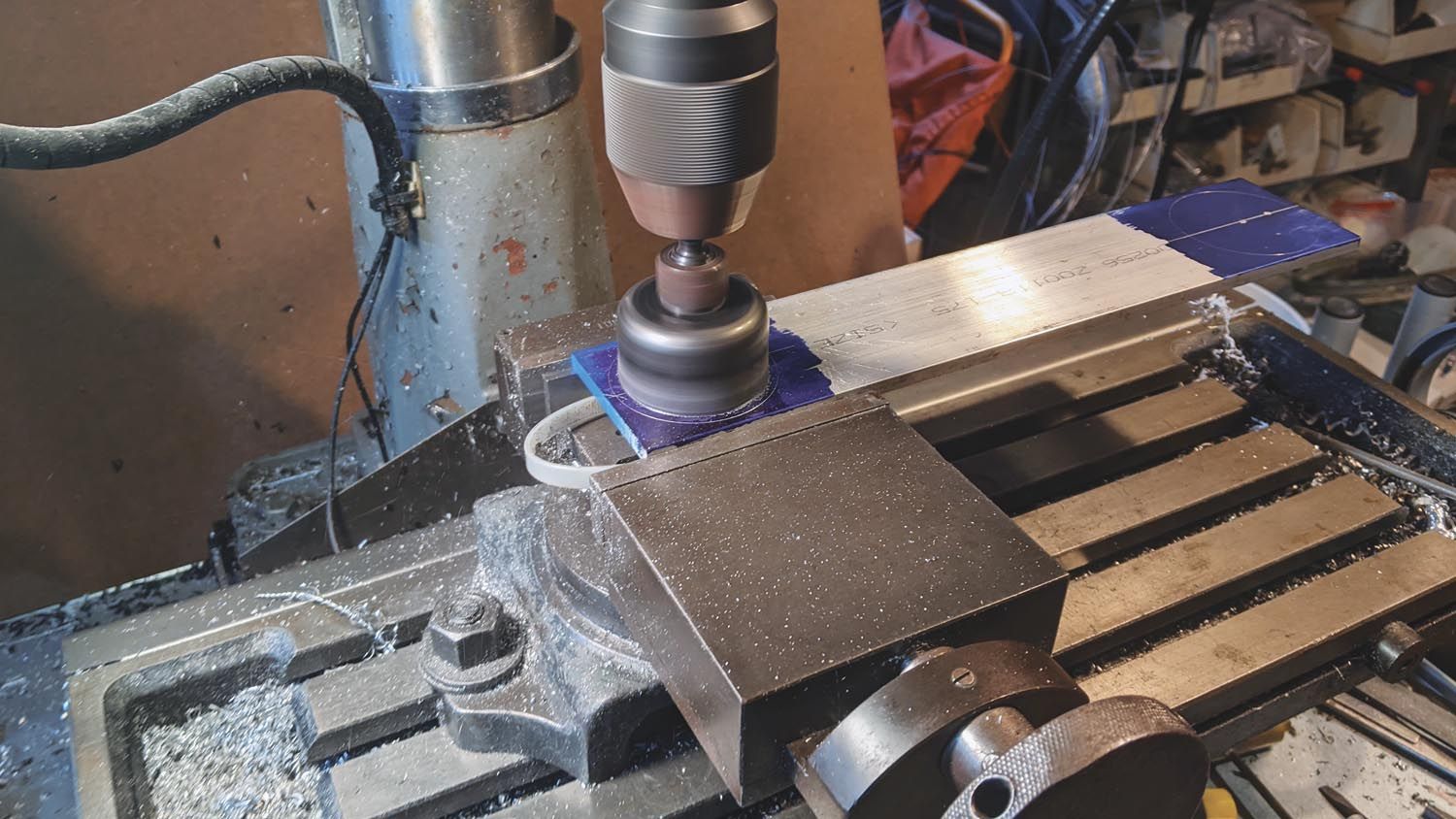
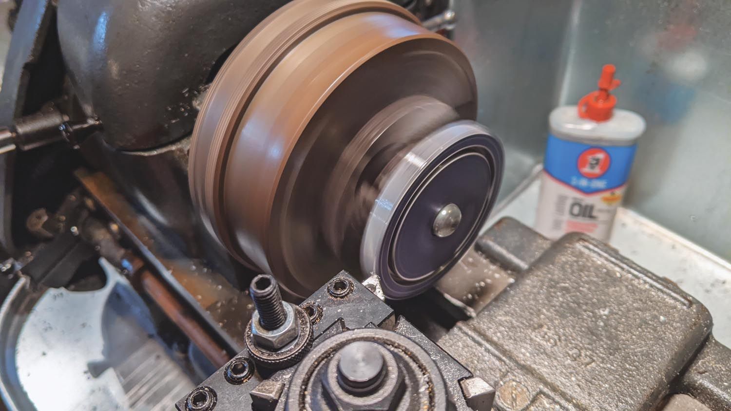
The design presented here can be made with minimal tools. A drill press and a saw capable of cutting the 2-inch tubing cleanly and perfectly square are the minimum, but like most things, better tools will give better results. The O-ring groove in the end caps can be easily cut with a standard 2-inch hole saw, which has just the right kerf to accept the O-ring and tube. The outside diameter of the end caps can be cut with a larger hole saw, or you can use a band saw or whatever else you have, or they can be left square. Of course, if you have access to a lathe, you may want to use that. I used the hole saw to cut the O-ring grooves, but as I didn’t have the right size hole saw for the outer cut, I cut the end caps out with a band saw, then mounted them on an arbor to clean them up on the lathe.
If you prefer to hard mount the separator to a flat surface instead of using the MS21919 tube clamps as shown, you can leave them square (and a little larger) and drill holes across them outboard of the O-ring groove for some longer AN3 bolts, shown as an alternate on the drawing. If you use this approach, increase the end cap thicknesses to ⅜ inch to give a reasonable wall thickness around the bolt holes. Another option would be to use 2½ x ¼-inch aluminum angle for the end caps, with the O-ring grooves cut into the horizontal flanges and shorter bolts through the vertical flanges (not shown).
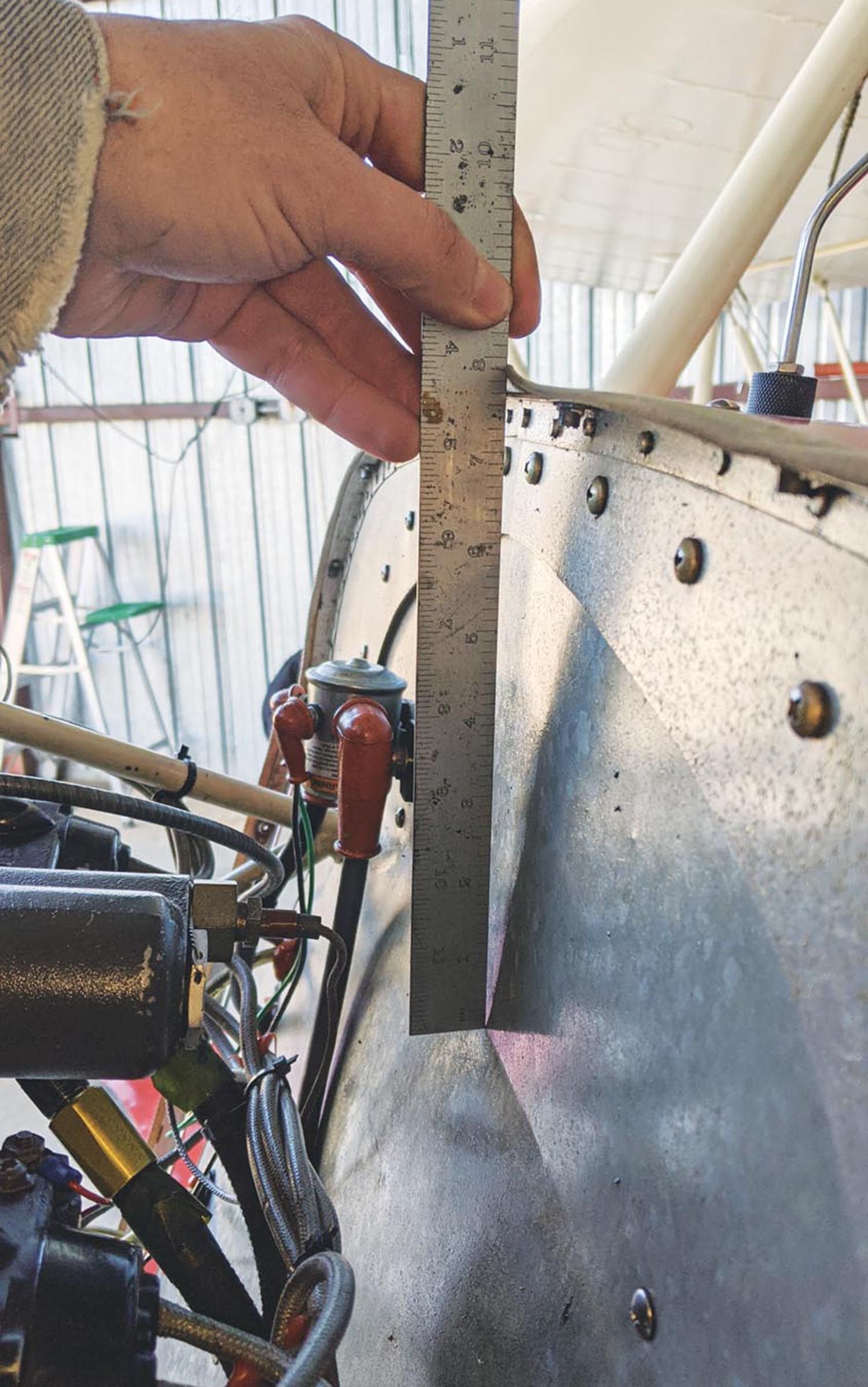
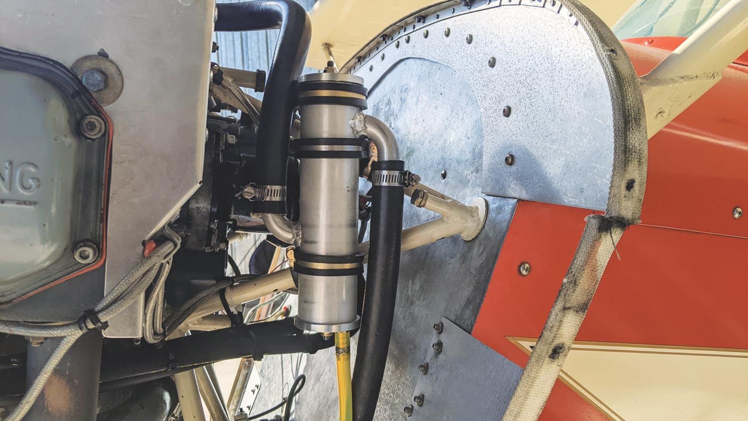
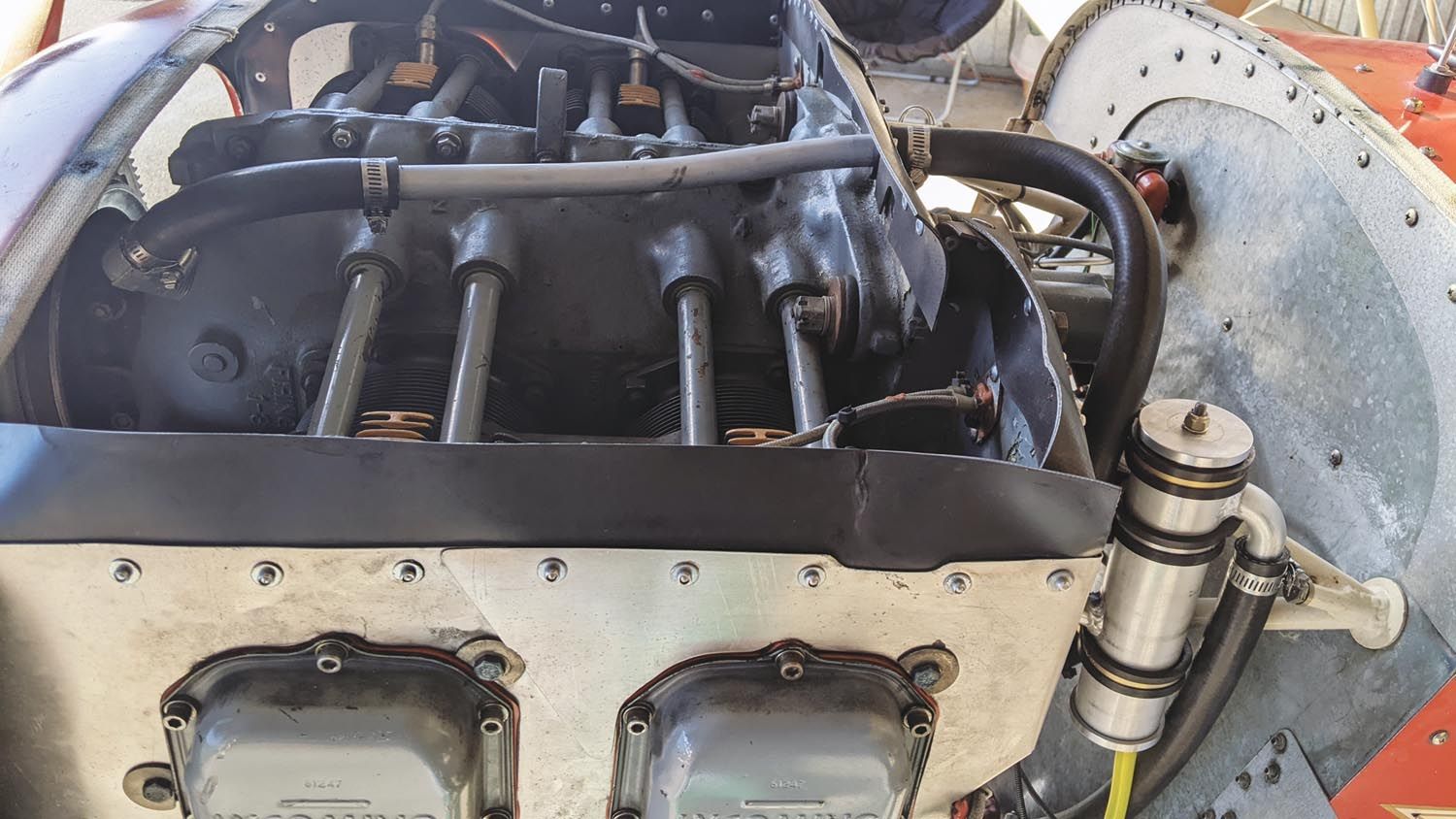
Before starting, decide where you will mount the separator and measure the available space. You may need to adjust the dimensions, none of which are critical, or orient the inlet and outlet tubes differently to suit your installation. It is best if the hose from the crankcase breather port slopes slightly upward to the separator, so any oil that coalesces in the hose before it gets to the separator can drain back down into the engine. I originally intended to mount it to the firewall, but space was tight and fuselage frame tubes right behind the firewall interfered with where the mounting bolt holes would have to be drilled. Mounting it to the engine mount tubes with cushioned Adel clamps put it farther up, which would help with the return line if I chose to go that route, and it also put it in a location where I could see it through the cowling air exit openings during preflight.
Mounting the hose fittings in the thin-wall tube presented some challenges. On the first unit, I used standard hose barb adapters; I pipe tapped the side of the tube and screwed the fittings in. The wall thickness wasn’t nearly enough to adequately hold them, though, so I then used JB Weld (which, despite the name, isn’t “weld” at all but ordinary epoxy strengthened with steel particles) to build up a fillet around the exposed threads on the outside of the tube. Despite looking crude, it was still holding up several years later when I sold the plane, but I wanted something more refined this time. I spent some time trying to work out a clever adapter block to use standard hose fittings without welding, as I lack the equipment to weld aluminum and prefer to make everything myself, but nothing I sketched was simple and clean enough to satisfy me.
Welding
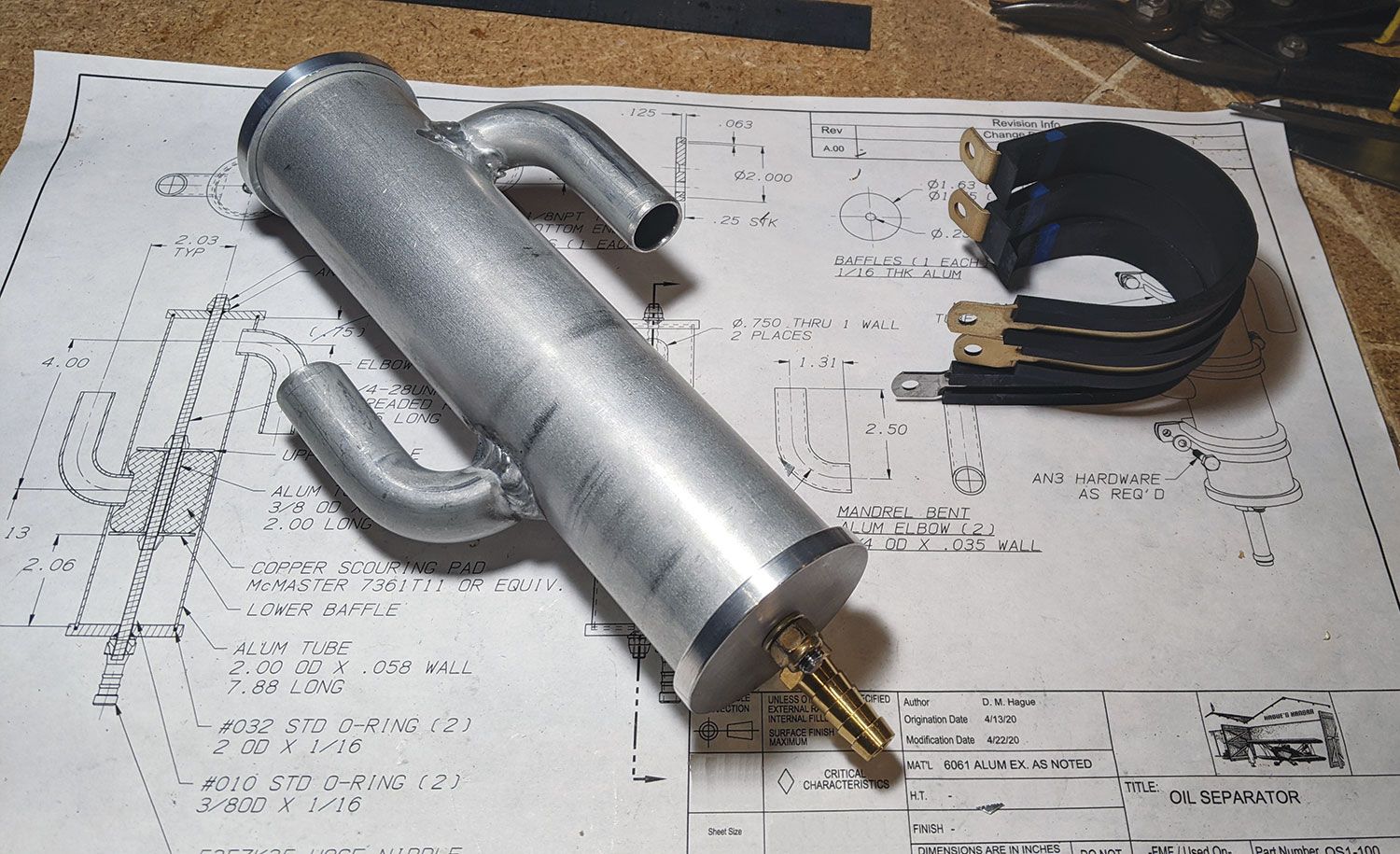
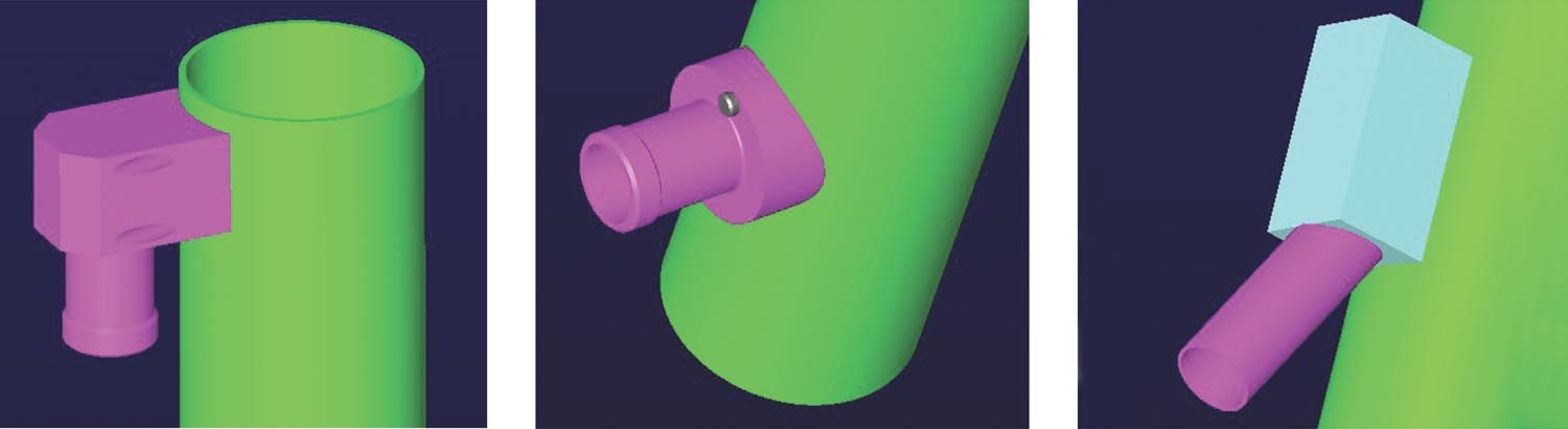
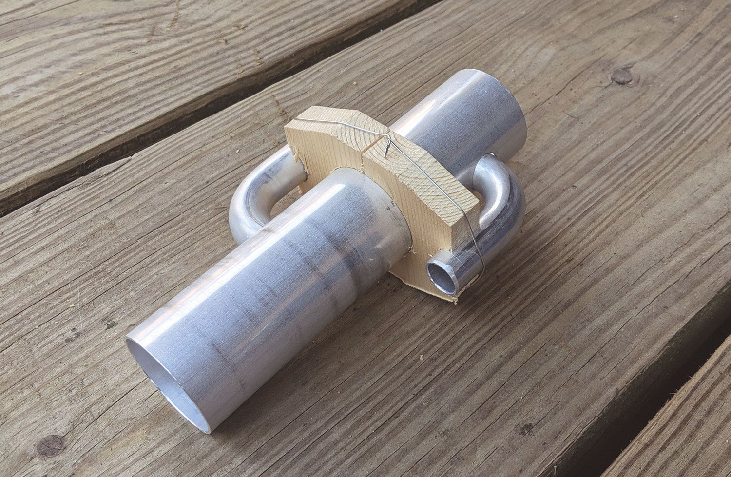
Finally, after finding some small mandrel-bent aluminum elbows for sale online, I conceded that a welded assembly using them would be the cleanest and lightest design, and my friend Joe, who had previously welded the new landing gear for my Starduster volunteered to do the welding for me. I used two 90° ¾-inch elbows from Verocious Motorsports. These were cut to size, with the inlet pointing up and the outlet pointing down, but depending on your installation, straight tubes or other angles might be better. Aluminum AN hose elbows or nipples could also be used, with part or all of the threaded portion cut off before welding to the tube. If you take that approach, be sure to clean off the anodizing in the area to be welded.
In either case, the welding must be done with care to avoid distorting the tubes. For the upper fitting, you may want to leave the 2-inch tube longer and cut to final length after welding to avoid overheating where the weld is close to the end of the tube. I drilled some holes in a scrap piece of the 2-inch tube and gave that to Joe along with the cutoff ends of the elbows to practice on. I also made some wooden fixture blocks to hold the elbows while they were tacked in place.
The upper baffle inside the tube is sized to give a somewhat larger open area than the ¾-inch hose feeding the separator, with allowance for the brass pad, so the breather airflow is not restricted. The lower baffle is larger, as it only needs a small gap to pass the slow drip of the coalesced oil into the lower chamber.
Assembly and Installation
Assembly is straightforward. Depending on the brass pad used, you may need to trim it a bit to fit inside the tube; I ended up cutting off about a third of it. It may be difficult to push it into the correct location if the stub of the inlet elbow projects too far into the tube. I used a strip of thin aluminum sheet to help it slide over the inlet and into position. Of course, that strip of sheet must be removed after the pad is in place. To get the last nut on when securing the top endcap, add a temporary extra jam nut against the bottom nut to keep it from rotating.
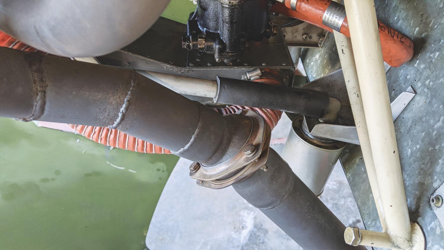
Attaching it to the engine mount was fairly simple, except for getting those &*#@$! Adel clamps closed to get the bolts through. I did have to change the routing of the ignition wires, which had been secured to the mount tubes where the separator would go. I spent some time figuring out how the piping would run and at one point wished I’d ordered another one or two of those nice little elbows, but I made it work with what I had.
After removing the old breather piping, which was a mixture of rubber hose and aluminum tube running down and under the engine, I needed to rotate the elbow that is screwed into the crankcase. Without removing the propeller and nose bowl I couldn’t get enough leverage with the tools I had in the hangar to even budge it, but I returned the next day with a large antique monkey wrench that had belonged to my great grandfather, which made it effortless.
I had purchased some ¾-inch aluminum tubing for the new piping, but after removing the old piping, I realized that if I cut the old aluminum tube in half the existing bends would work very well for the new setup. I drilled through the upper baffle, put a rubber grommet in the hole, ran the tube through it and joined that to the separator with a length of hose. A long spring inside that portion of hose keeps it from kinking where it’s bent. On the discharge side, a short section of hose connects to the aluminum tube running down to the bottom of the firewall, where a small 90° hose elbow points aft to maintain a slight suction on the system.
Down the Drain
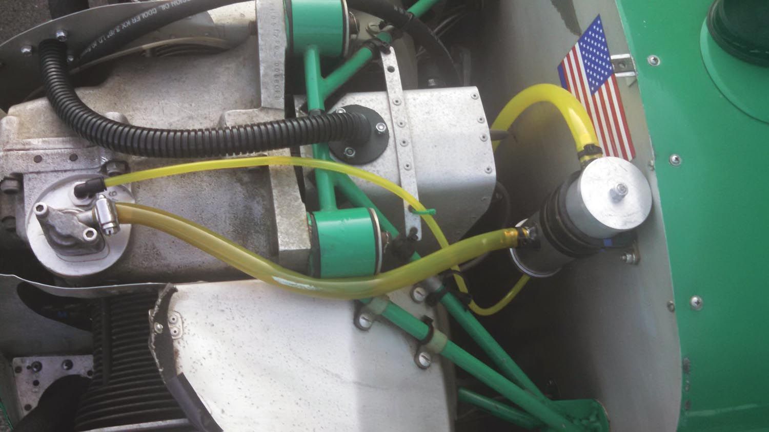
If you don’t intend to return the collected oil and the separator is accessible, you can install a petcock or quick drain in the lower end cap and drain it as needed. Since I would be mounting it up high where it would be inconvenient to reach, I used a hose nipple to drain the collected oil into a ⅜-inch hose, with the drain valve on the bottom. I initially used translucent hose (yellow Tygon “fuel and lubricant” tubing) so I could monitor it and drain when necessary, until deciding on the final configuration. I wouldn’t choose the transparent hose for a permanent installation as it doesn’t last that long and has no fire resistance, but I considered it adequate for a temporary setup where it could be easily inspected during preflight.
It Works!
Once the separator was installed, I immediately noticed a decrease in the amount of oil I was wiping off the bottom of the fuselage postflight. The amount I’m draining out of the separator is significantly less than the old catch can, indicating that keeping it warmer is indeed letting most of the moisture pass overboard as vapor as intended instead of condensing and mixing with the collected oil. There is still some water, though a lot less, and only in cooler weather. Because of that, and because the amount of oil collected is now much less, I decided that returning it to the engine wasn’t worth the trouble.
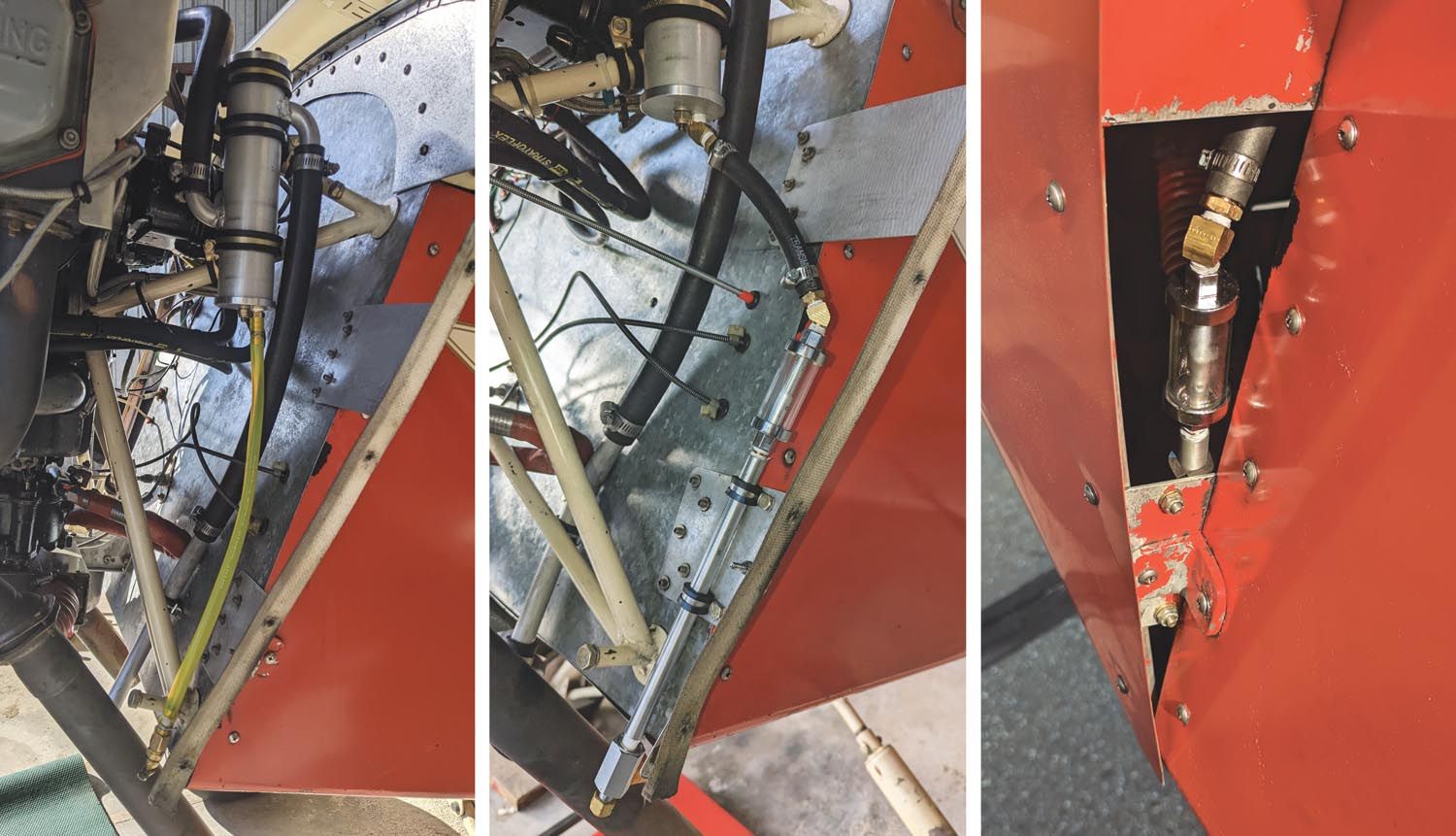
The only thing left was to use something more permanent than the transparent tubing. The final setup consists of a couple of 45° elbows, rubber hose leading to a clear glass tube fuel filter from the local auto parts store with the filter element removed, a length of ½-inch aluminum tubing threaded for pipe fittings on both ends and the drain valve at the bottom. The glass chamber is easily visible through the cowl air exit and won’t turn brittle or opaque with age like plastic tubing does. When liquid appears in the sight glass, I can drain it into a collection bottle without making a mess.
I designed the separator so it can be easily disassembled for cleaning, though I haven’t had to do it yet. As a precaution, at each oil change I disconnect the breather hose from the crankcase and blow into it to make sure the separator isn’t clogging. Fifty hours and two oil changes later, it’s still flowing free.