Back in 1993, I owned a 1956 V-tail Bonanza that had a 500-watt landing light installed in its left-wing leading edge and a 100-watt taxi light installed in the right-wing leading edge. When the 500-watt landing light was turned on during final approach, it lit up the entire landing zone from a half mile out. As the approach progressed to near touchdown, the entire runway and beyond was lit up. It was such a blessing to have that powerful landing light. However, that light drew 40 amps of current and pumped out an abundance of heat. You had to turn the landing light off the second the airflow over the wing slowed down or you would melt the plastic lens on the leading edge. Also, with the slower turning generator, the 40-amp demand drew current from the battery—but that old 500-watt incandescent light put out a glorious 387,000 candela!
I now have a GlaStar under construction in which I installed a 100-watt GE 4509 incandescent landing light in the cowling using the factory installation kit. It has been in the cowling for the last few years while the rest of the kit is nearing completion. It has always bothered me that I can’t have the light output that I used to have in my old Bonanza. The 8-amp current draw of this 100-watt lamp is the only benefit. It also bothered me that I had no taxi light and no convenient place to put a taxi light. My GlaStar has the optional auxiliary fuel tanks installed in the wings near each wingtip. The tanks fill the space, leaving no extra room for a Van’s style forward-spar installation of landing and taxi lights in the leading edges.
While scanning the July 2022 issue of KITPLANES, I came across Marc Cook’s article about modern aircraft lighting entitled “Light Show.” Marc’s article is a wealth of information for all sorts of LED lighting needs. My particular interest was drawn to the landing lights section with many manufacturers offering dual-duty landing and taxi lights in one fixture. One light jumped off the page: It was the Flyleds Seven Stars landing/taxi light putting out a whopping 588,000 candela! Actually, if you use the diffuser to achieve the taxi light function, the landing light only puts out 517,489 candela.
But wait—that’s about 34% more than my old Bonanza 500-watt lamp while offering a taxi light with just the flip of a switch. With a current draw of just 7.5 amps, I could use the same circuit breaker, add a double-pole-double-throw switch and install the Seven Stars in the same cowling mount. I thought I had found the Holy Grail of landing lights!
Stay Cool
The Seven Stars landing/taxi light has a highly efficient heat sink that extends out the back end of its metal core printed circuit board (MCPCB) about 4 inches. It is so efficient that Flyleds claims there is no power foldback, which is quite prevalent in other designs. Most competitive products have multiple LEDs that initially offer about double the light output of the 4509 sealed-beam aircraft light bulb but fold back the power to keep the LEDs from getting too hot. The result is that the light output drops to less than the 4509 in as few as 2 or 3 minutes of use.
The Seven Stars has the circuitry to protect its LEDs in the same fashion as the competing designs, but it uses a super heat sink that keeps the LED temperatures well below the 185° F (85° C) foldback threshold. The drawback is that the Seven Stars won’t fit in the same space as the original 4509 lamp; it is much longer and the circuit board has two flanges that extend out both sides to beyond the mounting tube of the original 4509 installation.
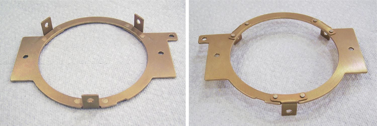
In order to use the Seven Stars in the cowling of the GlaStar, the challenge was to design an adapter plate that mounts the Seven Stars printed circuit board (PCB) while holding it securely in the original mounting tube with similar aiming adjustment capability. Using the dimensions of the Seven Stars PCB, heat sink and GlaStar mounting tube, a suitable adapter plate made from 0.090-inch-thick 6061-T6 aluminum and three mounting tabs made from 0.050-inch-thick 6061-T6 aluminum were designed and cut using a CNC router. (The CNC is not necessary; it is just an easy convenience to turn the drawing into hardware.)
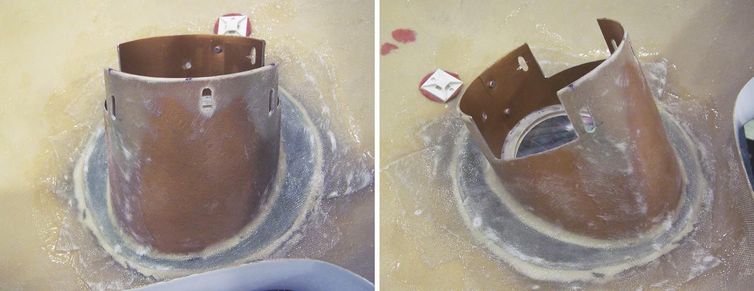
Modifying the Landing Light Tube
The next step was to modify the original landing light tube that was already glassed into the lower cowling. Two large sections of the tube had to be cut away so that the PCB and adapter plate could get the LED collimating lenses close to the cowling lens and still allow adjustment for aiming. This required a cut on both sides of the tube about 2.4 inches wide and about 1.32 inch deep.
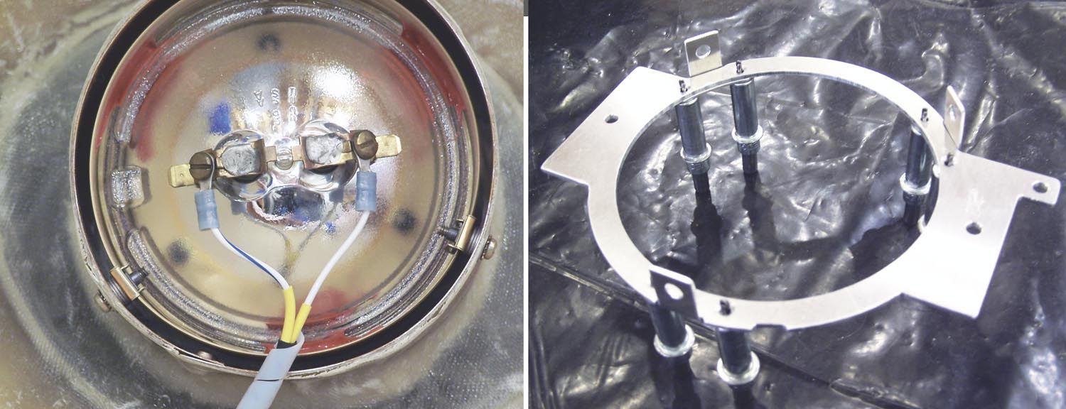
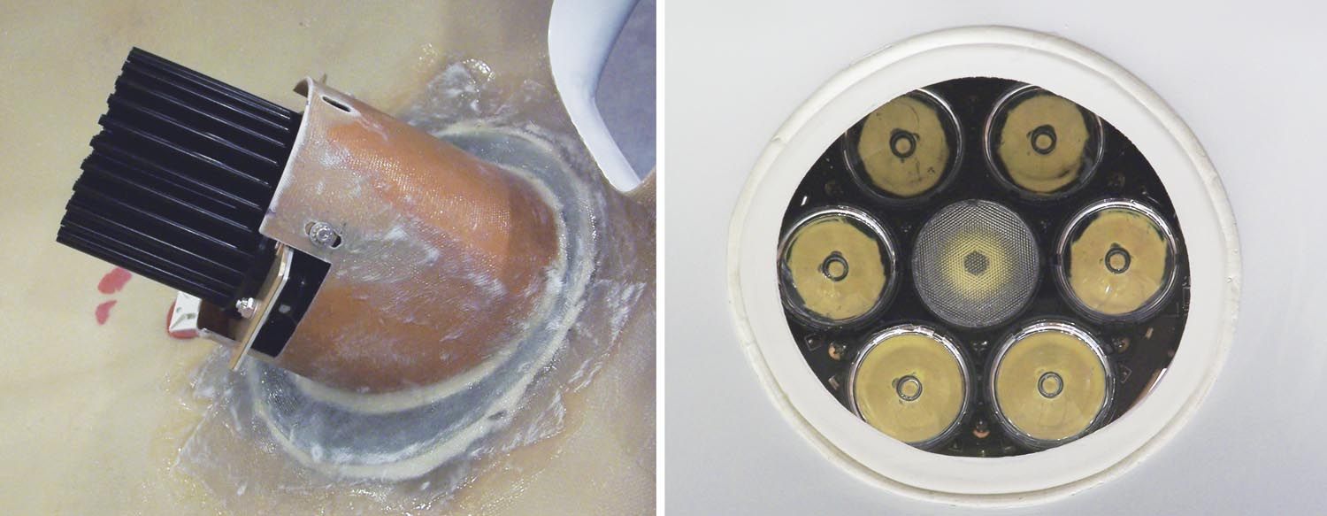
The tab mounting holes were slotted for the top two holes that are 104° apart, while the bottom tab mounting hole prevents movement. The bottom hole is the anchor while the top two slotted holes are used to adjust the light left/right, up/down or both. The GlaStar installation manual has you adjust the beam while the aircraft is parked on the ramp so that the landing light beam illuminates an area between 60 and 80 feet in front of the nose of the aircraft. This initial setting should be good to light the landing zone while on a 3° glide slope.
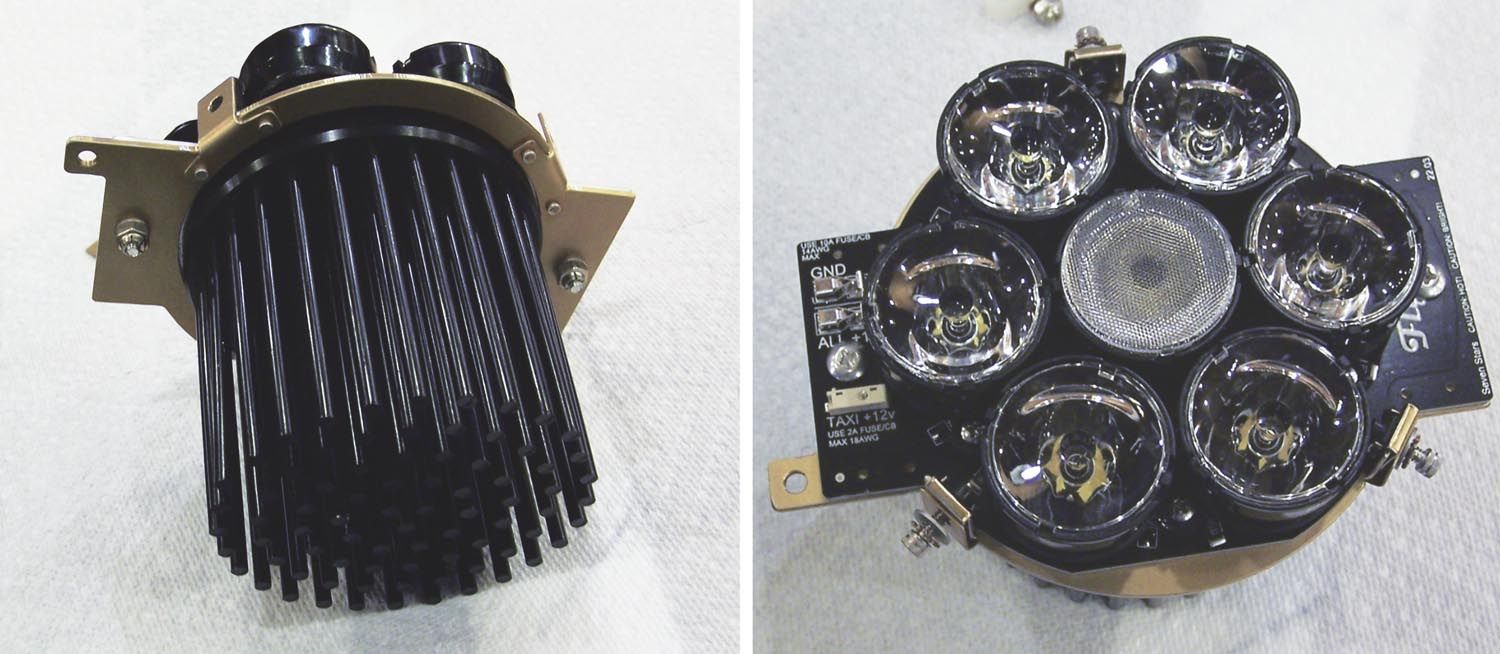
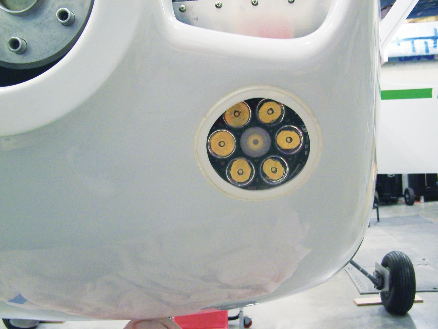
The location of the mounting tabs allows room for the NAS1352C06-8 Allen head screws to extend to full grip without contacting the collimating lenses of the Seven Stars LEDs. In the pictures, notice the Seven Stars light arrangement. The outer six LEDs and collimating lenses produce a spotlight beam in an 8° cone in front of the aircraft. The center LED with its diffuser lens produces a beam of about 30°. The center LED is used alone for the taxi light while the landing light involves all seven LEDs. When you include the 4500K to 5000K color temperature of these LEDs, the perceived light is much greater than the 517,489 candela would indicate. It is an absolutely awesome landing light!
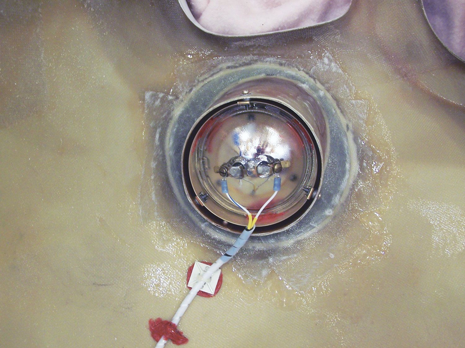
Wiring
Wiring the light is a simple task of providing the 14 AWG power and ground to the landing light function while sending the 18 AWG power (using the same ground as the landing light) to the taxi light function. All connections are available on the left wing of the PCB with simple push-in connections. I used shielded twisted pair wire for each function and provided a circular plastic connector for ease of removing the lower cowling. The shielding of the wires is to keep unwanted ignition noise from getting back to my power source.
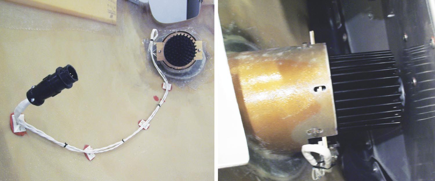
One of the better features of this lower cowling installation is the heat sink location, which is a full half-inch forward of the engine baffling. The air inlet for the cabin heat is right behind the heat sink of the Seven Stars. This inlet always has air flowing through it. When the cabin heat or defrost is on, the heated air flows into the cabin. When the cabin heat is off, the heated air is dumped overboard at the rear cowl flap. Thus, fresh air is always sent through the heat sink.
I can’t wait to finish the GlaStar and go fly this Holy Grail of landing lights.
Download the complete PDF drawings of the GlaStar cowling mounting tube, custom mounting plate and tabs, and the Seven Stars landing light parts GlaStar Landing Light Mounting Drawings.
- Read More: Building and installing Flyleds’ landing and taxi lights in a GlaStar leading edge.
- Watch: GlaStar Walkaround with Amy White


